This is the second in the build your own 3d printer kit series. This post details the build of the frame.
The first part of the series detailed how to put together the end stop wiring, the gears onto the motors and the initial build of the extruder.
If you missed the first part of the build then have a read of it here.
If you have got this far into your build and want to continue brilliant, let’s get on with it.
Build your own 3d printer kit frame build
section quick link
Just a little aside.
The allen keys supplied have almost a ball on the end of them. These are good and bad.
Good for the fact that you can angle the allen keys and don’t need to go in straight.
Bad for the fact that when you are not going in straight you can easily round or slip in the socket.
They are a very good invention, and have helped a lot of engineers to get out of a oops moment when they have placed the screw behind a pillar without thinking about it. Or have designed it that way!!
These pictures show the maximum angles you can get with these types of allen key as opposed to the other end which will only go in straight.
So to the frame.
Bottom frame
This consists of the 6 shorter metal extrusions along with 6 of the triangular ‘A’ moulded parts.
Starting with the moulded parts, assemble together.
5off M4X10
5 off M4 washers
5off M4 T-nuts
1 off M4 spring washer ( looks like a broken washer, but works like a spring)
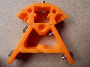
You fit 4 off the screws with washers on the two A legs and the t-nuts go onto the outside. You don’t need to tighten.
Make sure the t-nuts have the serrated shoulders facing towards the moulded piece or they will not do their job.
The job of these nuts is to secure themselves within the cavity of the metal extrusion. You are able to align the nuts with the slot and slip them into the slots. Tightening the screws the t-nuts will twist within the slot and grip onto the shoulders. This is an excellent and fast method of building and adding on parts to the extrusion system. So if you ever forget to add something you can always just insert the partially screwed up t-nut into the slot and tighten to secure.
The screw on the top of the A has the spring washer placed on the screw thread first, then the washer. This is inserted into the hole and the t-nut – with the serrated shoulders towards the head and placed into the moulded aperture screw it on loosely.
Use pliers if you need to to hold the t-nut in position while you start the thread.
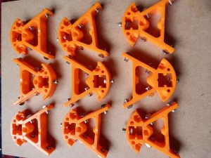
Repeat this another 8 times. You should end up with these.
Add drive motors
note: after assembling the whole printer I found that I could not align the belt straight. So I turned the gears on the motor shaft around.
To prevent you from having to do this in place, now would be a good idea to turn them around.
The thick part of the gear goes towards the end of the shaft. The screw still has to fit onto the flat of the shaft and the other secured.
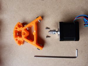
The three main drive motors hold the lower frames together before the uprights are fitted.
Take one of the A moulded pieces, two M3X8 screws and one motor.
Place the screws though the holes from the inside of the bar of the A.
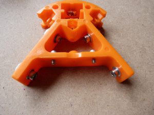
Offer up the motor so that the central piece fits into the cutout of the A frame.
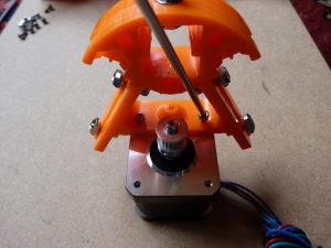
Using the allen key, very carefully screw the two screws into the motor. Stop if you have to use a lot of force as you may have cross threaded the screw.
If you do this remove the screw. Remove the motor and screw the screw in straight before trying to refit the motor.
It is a little tricky but persevere and you will get all three done.
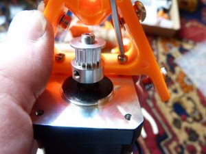
I found that if you rocked the A frame back a little after starting the screw it made it a lot easier. As I say just be careful not to cross thread the screws.
Now to make things interesting you will need to mount the other A frames on the motors.
Another two screw for each motor and a bit of bad language is allowed, but only if you want.
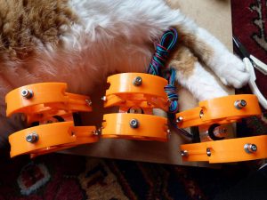
You should end up with three sets of motors mounted within pairs of frames.
I think the cat had really given up on inspecting at this point and just fallen asleep.
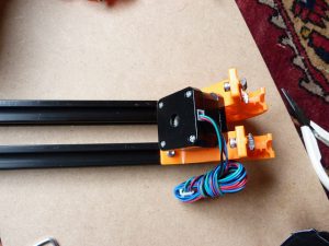
To mount the extrusions you align two of the t-nuts horizontally and insert into the slot of the extrusion. Use the allen key to tighten the nut.
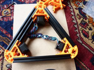
You may find that you will need to undo the nut further before you can tighten it properly in the slot. Yes sometimes they will fall off if you undo them too much – you curse, take the extrusion off and reassemble the screw. Remind yourself not to do that again – till the next time!!
Once you have done all six of these you end up with a bottom frame assembly.
Make sure you butt the extrusion up as tight as you can to the moulding, towards the corners.
Top frame
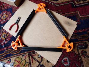
The top frame assembly is a little simpler.
Just three A mouldings with associated screws, nuts and washers. Three extrusions all fitted together in a triangle.
Again use a pair of pliers to hold the t-nuts in place while screwing the top screw into place.
Top bearings
The top bearings are fitted to allow the drive belt to loop around with minimum friction.
The drive belt is 6mm wide and it has been found that placing two flanged bearings with the flanges on the outsides allow the drive belt to run smoothly and not fall off.
So with this assembly we will be placing two bearings into the aperture above the bar of the A.
According to the manufacturer you should need
1 off M3 X 25
4 off M3 washers
1 off M3 nut
2 off flanged bearings
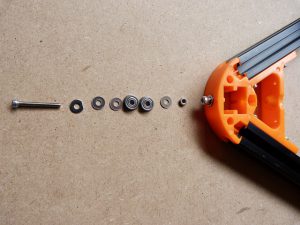
well I tried to fit this assembly into the aperture and failed.
So I measured it assembled.
It turned out to be 12.55mm.
The space it was supposed to go into was measured at 12.38mm.
I had come across my first problem.
So ok most logical thought the assembly was going to be screw, then washer, through hole, washer, washer, bearing, bearing, washer, nut.
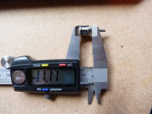
Hope fully you followed that.
So if we drop out one of the internal washers it should fit – the length is now down to 11.77mm, so it should fit.
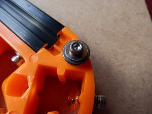
Screwing it together the bearings were binding.
What I found that was causing this was the washer size, it was catching on the outer race of the bearing causing friction.
With what this assembly was to do this was unacceptable.
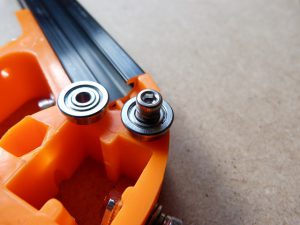
Looking at the parts supplied. I found that the M3 spring washer was a good fit for the inner of the bearing.
Now my assembly consisted of screw, washer, through hole, spring washer, bearing, bearing, spring washer, nut.
What you need is
1 off M3 X 25
1 off M3 washers
2 off M3 spring washer
1 off M3 nut
2 off flanged bearings
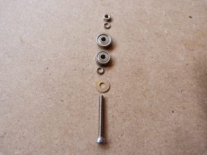
Will it fit length wise?
Using the vernier calipers and subtracting the the screw head and washer from the overall length it came down to 12.11mm when tightened.
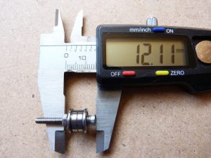
So yes it will fit and the bearing rotates freely when the nut is clamped up, unlike with the washers. When tightening the nut the bearings became stiffer and eventually stopped turning.
This assembly is a bit of a pig to fit with the spring washers and I fully understand if you go back to the washers and don’t fully tighten the nut to allow the bearing to move freely, but the way I assembled it was to align the spring washers and force the nut down.
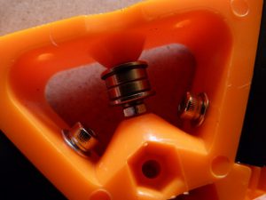
Try to do the screw up and this turned the whole assembly. You can then align the nut with the screw and tighten it down.
You only have to do it three times and to have the top bearing operating correctly I think it is worth it.
So good luck.
Leave a comment below if you did do it – or call me a name if you found this impossible!!
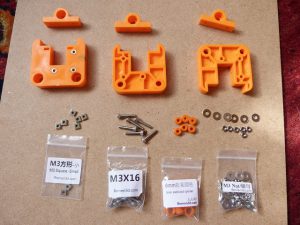
The next assemblies are the side carriages. These are responsible for the movement up and down the upright rails. They are tethered by the belt and carry one end of the effector rods.
I struggled a little with this assembly – I bet you can spot my deliberate mistake. If not I will tell you at the end.
What is required for this assembly are
3 off large side carriage mouldings
3 off adjuster side carriage mouldings
6 off M3 square nuts
6 off M3 X16 screws
6 off 6mm spacers
6 off M3 nut
6 off M3 washer
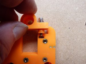
According to the manufacturer you place a nut onto the screw then a washer. This is then passed through the adjuster side moulding, fitting the spacer and is supposed to screw into the square nut inserted into the large side slide moulding.
Well as the picture shows I failed to get the screw to reach the nut.
So taking the nut off I managed to get the whole assembly to fit together
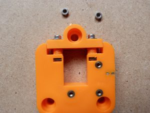
I wasn’t happy with the flat alignment of the two assemblies so I removed the flashing on the large moulding.
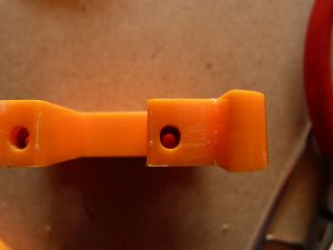
I then noticed that the square nut was stuck at one extreme of the oval hole. Nothing I did would make it lower, I tried inserting a drill to remove as much material as possible – with out drilling right through.
In the end what I did was to use a standard M3 nut in place of the square nut, this was able to fit lower into the moulding and allow better fitment.
I tried the assembly onto the rail and found that it was too wide. There was no way to screw it down to get it to run nicely onto the extrusion rails.
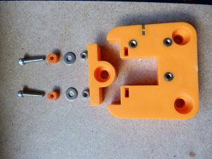
I ended up using the assembly shown in the next picture.
2 off M3 X16
2 off spacer
2 off M3 washer
2 off M3 nut.
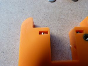
Place the nuts in the slots In the large moulding.
Place the spacers onto the screws. Pass these through the smaller moulding and place washers onto the screws.
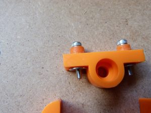
You can then align the screw with the nuts in the large moulding.
You don’t need to tighten these down as they need to be loose to fit over the rails.
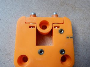
Oh make sure you fit the adjuster piece with the large hole on the same side as the large holes in the large moulding, otherwise you will be taking it off again to refit the correct way up.
I found that I was struggling with the hole size in the spacer so using a pair of mole grips ( vice grips) and a 3mm drill I cleared the holes in the spacers before fitting.
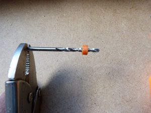
I found that I had to do this on a lot of the clearance holes. If you do this make sure you don’t clear a hole which is supposed to be for the screw to thread into. I will warn you which ones these are.
I also flattened the ends of the spacers to try to get the assembly to fit straighter.
Did you notice the deliberate mistake? On the first two pictures trying to fit the screws and spacers the adjustable moulding was on the wrong way round!! oops! I changed it to the right way round and it still didn’t fit, but was closer. So it didn’t matter in the end.
The next stage for this assembly is to add the drive wheels.
You will need
3 off M6X30
6 off M6 nuts
3 off M6 spacers
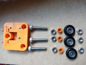
3 off drive wheels
The assembly of these is to place the screw through the hole so the head is into the recess.
Tighten a nut onto the other side of the moulding.
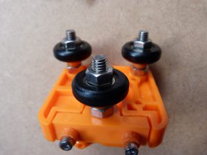
Fit one drive wheel on each screw and then fit the nut to retain it.
Again here I found the nut corner width was too great for the bearing and was slightly interfering with the rotation of the bearing.
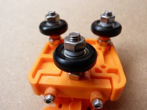
So what I did was to design a simple spacer and print it off on my other 3d printer, yeah I know this is your first so what can you do?
Well I would put it all together and the spacers would be the first thing I printed out. Can you retro fit – yes you can. Taking the nut off one by one and fitting the spacers before removing the next nut, you should be able to do this. Just don’t fully tighten the nuts down onto the bearings.
I have included the stl file here so if you want to use this you can.
The first print you do should be a simple one which doesn’t matter if it goes slightly wrong, so this is ideal.
The belt retainer is fitted to the inside of this assembly.
You need
3 off M3X8
1 off moulded piece
3 off M3 washers
With this moulding screwed straight down onto the main assembly I found that it was interfering with the operation of the slider adjustment.
This is back to the adjuster not being level before the screws are tightened.
When the slide assembly is fitted to the rails you will find that the adjuster will always be out of alignment.
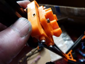
So I spaced the belt retainer off from the main moulding with washers – I did print out some M3X1mm spacers, but there are enough M3 washers to do the job.
So as shown in the picture, insert the screw through the moulding and then place a washer before locating it onto the main moulding.
Uprights
The three uprights are fitted next.
These are three longer pieces of extrusion.
They are located into the bottom frame assembly.
Carefully align the t-nuts so that the extrusion can slide down into the hole in the A piece.
Tighten down the screws to retain the uprights.
Wobble them at the top gently to see that they are secure, and if necessary loosen the screws and re-tighten to secure them.
This is when you want to select which upright is going to be which.
To a certain degree it doesn’t matter at the moment, but later on in the build you will need to orientate the printer so the electronics, and some of the hardware is in a certain position.
I don’t agree with the way the manufacturer says to label the uprights but it is encoded into the software.
They have used the three axis notation of X,Y and Z.
This corresponds to the front left, front right and rear respectively. Looking at the printer.
Use pieces of tape and write on them. Also at this point do the same with the motor cables, label them near the connectors – so when you put these onto the controller board you know which is which.
The side carriage assemblies can be tested on the upright rails.
You may as well fit the adjuster screws now to the carriages.
You will need
3 off M3X16
3 of M3 nut
screw the nut onto the screw far enough so that the screw can be fitted into the hole in the side of the carriage.
Use the nut to lock the screw from turning by tightening the nut down onto the carriage moulding
This is for end stop adjustment, to allow the print head to be centralised.
Fitting the side carriage with the single hole at the top.
Adjust the adjuster screws so that the carriage will gently roll down the upright unassisted.
You don’t want it to just fall straight down with a crash, but you want it to take a few seconds to get to the bottom. You also don’t want to push it to get to the bottom.
This is where you will see that the spacing of the belt retainer comes in, as shown in the picture, if the washers weren’t there then the adjuster would not have enough movement to allow free travel of the slide.
Limit switches
The limit switch assemblies made up in part 1 of this build can now be placed onto their respective mounts.
Using
2 off M2.5X12
1 off M4X10
1 off M4 t-nut
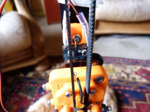
The M2.5 are a tight fit into the holes in the end stop switches so be careful when fitting. Fit the switches with the wires coming towards the slot in the moulding.
The middle contact pin for the switch interferes with the mounting of the end stop bracket, so bend it carefully out of the way.
The end stop carriages want to be mounted about 30mm down from the top of the uprights. Use a strip of stiff paper or card marked with a distance to align the switch mounts.
I find that if you bend the card and place it on the top of the upright you can butt the end stop bracket up against this. Repeat for all uprights.
Don’t forget to label the end stop switch wires near the connectors with te same letter as the upright it is on.
Top frame assembly
Now you can start to make it look like a printer and see the shape of the whole. We are going to be mounting the top assembly.
You should have already made this assembly, as shown above.
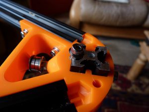
Make sure that all of the side screws are still in place, and add the angled screws.
You need
3 off M3X30
3 off M3 nut
3 off M3 washer
Fit the M3 washer over the M3 screw and pass through the angled hole in each corner for the assembly.
There is a nut aperture in the bottom of the assembly for the M3 nut so tha assembly can only go one way.
Do not tighten this screw fully.
Align the holes and t-nuts for the uprights and gently ease the top assembly over the uprights.
Using the screws just fitted adjust them so that the top assembly is 5mm down. I used the paper trick I said about above. ( mark it 5mm from the edge and bend it over – butt the top assembly up to this using the screws)
now tighten the outside screws.
Wiggle the top assembly to ensure that the t-nuts have caught and are holding it in place – you can also use a torch looking down the extrusion.
Sit back and smile, as this is how big your printer will be.
Belt installation
The 3d printer requires that the circular motion form the stepper motor is translated into linear motion to move the side slides.
This is carried out with timing belts, GT2 belts to be exact.
These are 2mm pitch ( note the 2 in GT2 is a reference to the second generation! You can get 3mm pitch GT2 belts!), with a rounded profile rather than the standard profile on most cars – which is trapezoidal.
Why use the rounded?
Well it has less backlash, unwanted movement when changing directions.
It is quieter, always good.
Has less wear, again good for the life of the product.
You don’t need as much tension on the belt as with a flat or trapezoidal one, good for low slippage.
As this belt is reinforced with glass fibre, as with your timing belt on your car do not twist it if you can help it. Twisting it may break some of the reinforcing fibres, shortening it’s life. Do not bend it back on itself – again you may damage the reinforcing within the belt.
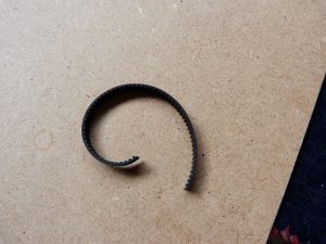
The belt supplied with the kit is just long enough.
I didn’t cut it into three pieces as advised, I fitted each upright with the belt and the length left is 130mm ( about 5 in).
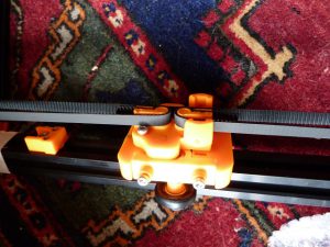
The way I fitted the belts is to take the loose end and feed it through the motor sprocket up and over the idler pulley in the top assembly and back down to the side slide. Affix the loose end into the ‘P’ shaped area on the side slide. The tail goes around the rounded bit and down the back of the ‘P’. Then pull tight and shape the belt around the other ‘p’ shape before cutting to length. I left about 10mm (½ in) sticking out of the ‘P’ shape. Make sure the belt is fitted onto the motor sprocket and in the idler pulley before cutting the belt.
Repeat this for the other two uprights.
This is where you need the room as I laid the printer down to do this and had ‘swing’ room as I was moving it around.
You won’t be able to get the belts very tight as I found that pulling on the belt only caused the slide to move up and down. Just don’t have it slack enough to slip on the motor sprocket.
Spring tensioner
There are springs supplied with the kit to tension the belts. These look like they are from clothes pegs.
These have been put forward as a way of tensioning the other types of printer, I have looked at them and thought that they will lose their effectiveness when the mass comes to a stop ( being a spring) and allow the slack to overshoot before snapping back and re-tensioning the belt.
With this printer design, I think there is less moving mass so they may be more effective. So I have fitted them at the moment, until I get some results from the printer and have a few months of experience with it, I won’t be able to tell the effectiveness.
So how do you fit them?
You will need a pair of smallish pliers, mine have a nose width of about 8mm (1/3 in) you could use larger ones but they may get in the way. You can’t do this by hand, so you will need something to grip and twist the spring with.
So to start with you hook one end on the spring over the belt, the spring part is on the other side of the belt, this can be done by hand. Make sure that the little folded end piece comes around the belt.
Now using the pliers grasp the not fitted end and twist the end around the belt, so the end goes onto the other side of the belt to the spring part.
When you release the pliers you may have to straighten up the tensioner to make it look like the third picture.
Repeat this for the other two, the belts should be tighter now.
Spider
The middle piece which carries the hot end is called the print head. This is controlled with effectors – items which cause an effect- the rods connected between the print head and the side carriages.
All of the rods need to be the same length, so it is a good idea to check them now, along with the movement of the fisheye joints. They should be free to rotate in all directions with no binding.
I have heard it being called a spider due to the look when all of the rods are connected to the print head it looks like a long legged beast.
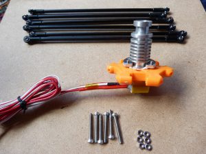
To connect the rods to the print head you need
6 off M3X25
6 off M3 nut
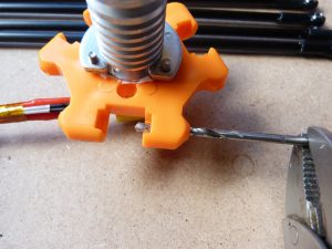
You may need to clear the holes to allow the screw to fit through easily, so use the 3mm drill held in the mole grips to carefully clear the hole.
With the fisheye you have a large flat and a small flat. I mounted these with the smaller flat towards the print head and the larger flat against the screw head.
Unscrew the top connector to remove the black printed shroud. This shroud with a fan fitted cools the metal above the hot end and also cools the extruded plastic once it has come out of the nozzle. With out effective cooling of the metal above the hot end the filament may melt too far up and cause a blockage. Without effective cooling of the filament, this can melt the previous layers causing blurred printing.
Pass the screw through the fisheye – in the right direction. Then through the print head and place the nut over the end and tighten.
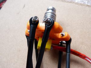
Repeat for the other five effectors.
Mounting the spider in the printer is a matter of fixing all of the effectors to their relevant side carriages.
You need to make sure that the flat on the print head hot end is pointed towards the Z axis upright – unlike me when I first put it together.
To fix the effector rods to the side carriages you will need
6 off M3X18
6 off M3 nut
Push the side carriages towards the top of the uprights to make it easier to fit the spider. Make sure that all of the side carriages are all about the same height.
Use the drill to clear the holes if necessary.
Fit the screw through the fisheye and then through the carriage.
Fit the nut to the inside and tighten.
Repeat for the other five.
Push the print head back towards the Z upright.
Refit the black printed shroud, with the tow nozzles towards the x upright and y upright.
Screw in the quick fit connector to secure it into the top.
You should now have the print head suspended and able to move within the area of the print volume.
Auto level
The auto level switch assembly allows the printer to automatically take measurements to take into account any slope on the build platform.
On my old Prusa, I have spent many happy (?) hours adjusting the build platform trying to get it level and then finding that there was a small amount of filament sticking out of the nozzle. Redo from start. The first layer will not stick unless the nozzle is within 0.2mm of the build platform across the whole area. But you don’t want it too close either as this stops the filament being extruded.
Any automatic help you can get from the printer to make your life easier – take it.
The auto level mechanism is made up of a bracket, which you can swivel half of. And a microswitch.
When the switch is lowered this is below the level of he nozzle so that it touches the build platform first.
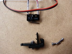
To carry out printing the switch is rotated out of the way so the nozzle is the lowest item.
To fit the microswitch you will need
2 off M2.5X12
Carefully screw the screws through the microswitch and into the lower part of the bracket.
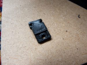
There is a step on the lower bracket, I first had this on the inside and the microswitch never hung correctly.
I changed it to being on the outside and then the microswitch hung straight down.
I also put the microswitch on the outside, this appeared to work more effectively and I am able to swing it out of the way when it is not needed.
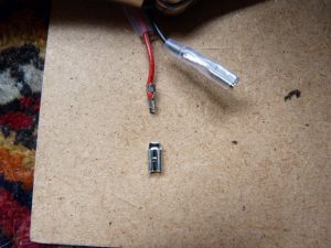
Whilst doing this I managed to bend one of the push on connectors for the microswitch. Straightening it I managed to break it. These can be resoldered together with a little care and be reused.
To fit the auto level assembly onto the print head, you may have to sand or file the sides of the printed bracket. Mine would not fit into the area required.
Note to fit this you will need to remove the quick coupling fitting and the fan shroud- again!
You need access to a screw hole under the shroud.
Once the bracket is the right size I found the easiest way to fit it over the effector screws was to undo them.
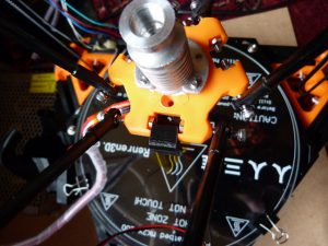
I unscrewed them to level with the nuts, then pushed the autolevel assembly into place with the long tag under the print head. I screwed the M3X8 into place.
The two screws for the effectors were then tightened and the threads went under the bracket.
I am still not sure about this assembly as I feel that the screw is hitting the hot end. This will be disastrous for the auto level bracket as it is made out of PLA. It will melt as the screw gets hot. The heat will also travel up to the print head and also deform that. So I may be coming back to this in the near future.
Replace the fan shroud and the quick coupling.
The fan can be fitted at this point with two M3X18 screws.
Run the wires for the fan and the microswitch in with the wires for the hot end.
Extruder
The extruder assembly is fitted next.
I found it convenient to fit it onto the Y upright.
I had fitted it to the X upright but all I saw was the back end of the motor. This would have made it difficult to feed the filament into the extruder.
To fit the extruder you will need
2 off M4X10 screws
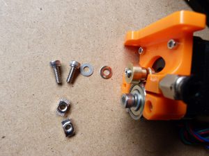
2 off M4 t-nuts
If it is not already fitted, screw in the quick fit coupling to the top of the extruder.
Assemble the screw loosely, as they will be fitted to the Y upright rail.
Align the t-nuts and fit the extruder about 30cm up ( half way up).
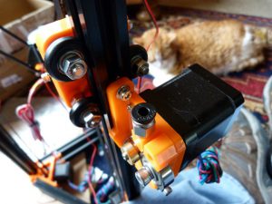
You need to fit this on the outside – so it doesn’t interfere with the running of the wheels down the sides of the extrusion.
PTFE tubing
The PTFEtubing is used to guide the filament from the extruder to the hot end.
Why PTFE? Well with the low coefficient of friction ( it’s slippery) it doesn’t take too much force to feed the filament from the extruder to the hot end.
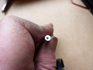
You need to make sure the ends of the tubing are not deformed or the filament may bind at that end. PTFEalso has a high melting temperature, so is compatible with the hot end.
Hot PTFEhas a curious effect on me, it makes me feel like I have a cold coming. It is just a reaction to the hot PTFE fumes.
If either end is deformed then taking care, use a sharp knife to slice the end at right angles.
The PTFE tubing is pushed into the quick connect couplings.
The coupling on the extruder, the PTFE goes in about 10mm.
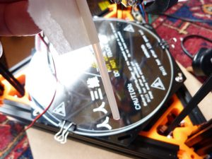
With the hot end you may want to place a piece of tape about 55mm back from the end. This is how far it should go in.
There are a few places where it can catch within the hot end so until you are used to how far it goes in use the tape as a guideline.
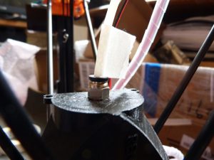
To insert the tubing, I tend to push down on the plastic part at the top. This frees the pipe to slide easily into the coupling.
If you need to remove the pipe ensure that you push down on the plastic top piece all the time you are withdrawing the PTFE tubing, releasing this will cause it to bind and may damage the tubing.
PTFE is a soft material and can be damaged fairly easily. So be careful with it.
Heated bed
To allow the printer to operate you need a build platform. You can have a glass plate fitted to the bottom frame and print directly onto this. This will limit the materials you can print with to low shrinkage materials.
As the filament is coming out of the hot end it is about 200C, when it is deposited onto a glass plate at 20C there will be an immediate cooling effect. If the material shrinks too much as it is cooling it with either not stick to the glass plate or it will curl as it cools rapidly.
To combat this and allow many more materials to be printed a heated build platform is preferred.
This is the black plate with wires attached to it.
To fit this you will need
The items included in the hot bed screw bag.
You will have
3 off M3X15 screws
3 off M3 t-nuts
3 off M3 washers
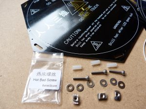
3 off M3 spacers.
The assembly of the items is to place the washer onto the screw and pass this through from the top of the hot plate. The spacer is placed on next with te t-nut holding it all captive.
As with all the other t-nuts don’t tighten this down at the moment.
I placed mine on the lower frame with the wires coming out towards the Z upright.
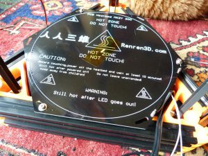
Find a place where all three of the t-nuts will drop into the slots and tighten the screws.
I didn’t want to crush the spacers to that degree so at present my hot bed is still loose. I will be making something to fix it properly once I am printing.
Wow! if you have made it this far you can sit back and look at an almost complete delta printer, all that is left is fitting the electronics and setting up.
Well that’s enough for this post I really appreciate you following so far. Put a comment below if you have got this far into the build your own 3d printer kit series and are looking forward to finishing and using it.
Be back with the next in the series – the electronics soon
Phil
