Make your Ramps 1 4 connections safe for upgrading your Anet A8 3d printer.
Ramps 1 4 connections upgrade
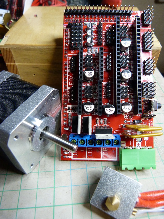
The ramps 1.4 board combined with the mega2560 is a common upgrade when the main board blows up on your Anet a8 3d printer.
It is not that you cannot get the original boards , but that the ramps, when programmed with marlin, gives you a lot more opportunity to upgrade your printer.
This is not without problems, one of the main ones I keep seeing on forums is the overheating of the connectors.
For the Anet A8, with it’s high current demand, the standard connectors are not good enough for the long term.
Yes they might work in the short term, but they will overheat and possibly catch the insulation on fire.
Can you safely use the ramps 1.4 on an anet a8?
You can replace the input connector, along with the bed, nozzle and fan connectors with ones suitable for the job.
I have looked into this and found a connector suitable for 20A continuous use.
It is a screw connector again, so you will need to check the tightness on a regular basis, but with this simple maintenance it will serve you well.
It takes away the pluggable input, but for the safety you get with this connector then to me that if justified.
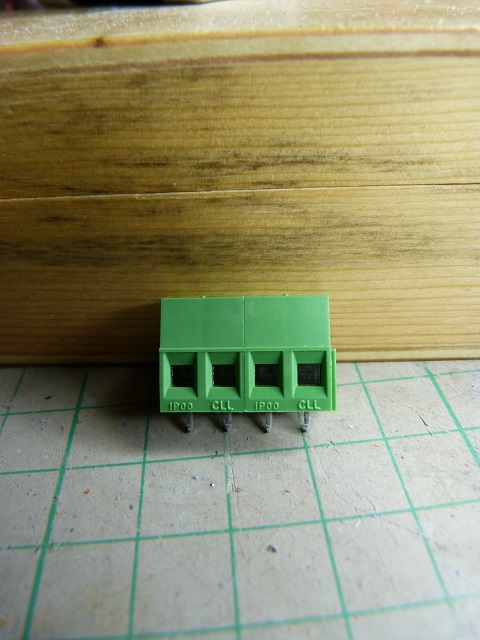
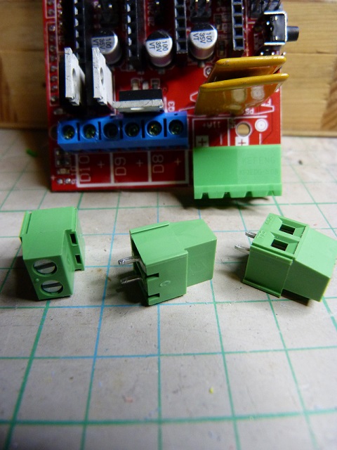
It is a pcb screw terminal connector from camdenboss cbt0158/2 (ebay link)- it is a 2 pole stackable connector able to handle 20A continuous.
So this means you can make any length of connector you want as long as it is in multiples of 2 – so 2,4,6,8 etc.
We are looking for a 4 way and a 6 way, so it is ideal for this.
How do you replace the connectors?
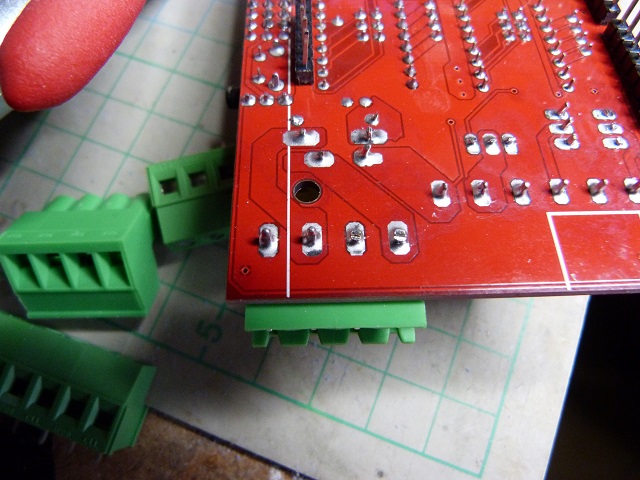
You will need to de-solder the input connector and the output connector along the one side of the board.
I started with the input four pin connector.
You will need a soldering iron, solder, pliers, solder wick or solder sucker and flux cleaner.
Start by clearing your workspace, and if you have a helping hands then secure the board in this upside down, with the connector pointing towards you.
Dependant on how the board has been designed, with or without a lot of clearance for the pins, for me determines how the connector is removed.
If there is a lot of clearance on the connector pins with the plated through hole then you can heat each pin up and clear the solder from around the pin with the solder sucker. If it is tight then I tend to add solder to each of the pins and heat along the row so that the whole connector can be slid out with the molten solder allowing the pins to slide out, then you clear up the solder.
Normally I tend to use the latter technique on pins that are closer together, but I tried to clear one pin to see that it was quite a tight fit, so went ahead with the flood removal technique.
I will probably get shouted down for this technique, but I have used it in my last job with no problems.
What I do is to heat each pin of the connector and feed more solder onto them.
You then go along the row heating each pin up until the solder melts again.
You will need to keep doing this until you see all of the solder around the pins becomes molten at the same time- I will lay the soldering iron down to touch as many pins as possible at one time to help this technique, feeding solder on as necessary to keep good thermal contact without oxidisation.
You can hold the connector in your hand and put downwards pressure on it to see when it comes loose, don’t pull too hard as this can damage the plated through holes – even rip them out.
You might find that it takes a couple of minutes to carry this out, depending on the wattage of the iron you have.
Mine took 30 seconds of going between the pins to get them all hot enough to remove it easily.
After the connector is out you will need t remove the excess solder with a solder sucker and solder wick.
Make sure you clean off all of the flux before you fit the new connectors.
The new connector is a modular one and fits together making up connectors in multiples of two.
So we will need two pairs for the four way connector.
They slide in with the dovetails keeping them tight together.
Once you have made up the four stack and cleaned out the holes for the connector you are ready to fit it.
sliding two togethertwo fully home to make a 4way conn
What I tend to do is to push the connector in – noting how tight or loose it is, ensure you fit it the right way round so you can fit the wires into the connector.
Push it all the way home – if it is really tight then stop – remove it and examine the holes – you may find a little bit of solder left down one of the holes. Clear this out and try again – never really force it in as again you have the chance of damaging the plated through holes and causing a problem of no connection on some pins.
Once it is all the way home, solder one end pin and stop.
Now look at the connector and see if it is still in the right place or has it moved – it is normally trying to fall out at this time as it is underneath the board with no support.
To readjust the connector heat the solder up and once it is molten readjust the connector to its right place. Stop heating the solder.
Check it again and once happy solder the other end pin, and check once more before soldering the rest of the pins.
Make sure you refresh the solder a little on the first pin to ensure that there isn’t a dry joint trying to form due to overheating the solder while adjusting.
Now clean off the flux with flux cleaner, IPA or acetone.
You have successfully replaced the input connector with a 20a one, congratulations.
All you have to do is to remove the 6 pin one for the heated bed, nozzle and fan.
This one you can try the same, but I found that with the pin pitch and the number of pins I couldn’t get all off the pins molten at the same time, so resorted to the solder sucker and once all of the visible solder had gone removed the connector.
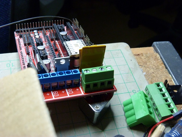
I constructed a 6 way connector out of three pairs and dry fitted it into the holes.
I found that the locking parts on the connector next to the power connector were interfering with the fit, so took a scalpel to them and removed them.
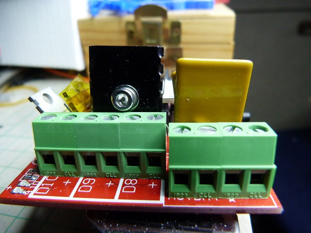
The connector now slid into the holes and was fitted tight to the board.
Turning it over I soldered one pin and checked the connector, this time it hadn’t moved so I soldered all of the pins and cleaned off the residual flux.
You could cut the original connector into a 4 way and refit that, but I felt it was too much hassle and just used all 6 of the new connector.
The wires to fit into the holes are stripped a maximum of 8mm – so I would pick 5mm as a good length.
The connector can take a wire size of 0.2 to 2.5mm stranded and 4mm solid, or 30-12AWG.
So you now have a modified ramps 1.4 board with connectors suitable for the job, they can handle 24A IEC or 14A UL – so dependant on what spec you want to use depends on what maximum current it can handle.
Why is this – well it is to do with the allowable temperature rise of the connector, UL allow a 30C rise in the temperature whereas IEC ( vde and imq) allow a de-rating curve of temperature against current and the specs are a little different.
If you have a different way or any comment on this article please leave it in the comments box and I will get back to you.
This has been an article about upgrading the Ramps 1 4 connections, replacing the connectors to suit the Anet A8 3d printer current, preventing melting or fire hazard.


 (ebay link)- it is a 2 pole stackable connector able to handle 20A continuous.