
What a digital multimeter can tell you.
You know that time when your printer went wrong and you sat there looking at it?
You were frustrated because you knew it was not mechanical, there was something wrong with the electrics or electronics.
Someone on a forum said – ‘ Have you checked the voltage at …’ and you thought huh?
Well that was the time when you could have done with a multimeter to measure the voltage.
The problem got solved eventually with a friend coming round with a meter and with a couple of checks he said ‘Yep I agree with them, it is the …’.
You just sat there and nodded.
So why not change that?
You know how to put the printer together and operate it.
You have had a go at the cad thingy they are all talking about, and yes it’s ok – maybe with a bit more practise it will get easier.
But what if it goes wrong again?
What will you do then?
Well you could do worse than invest in a multimeter – or meter for short.
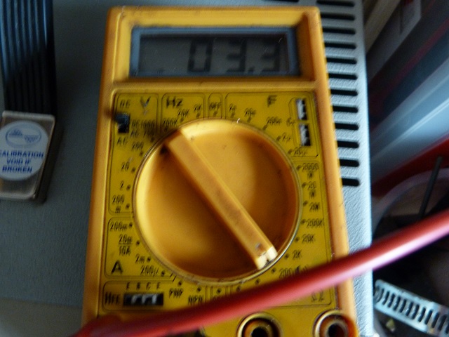
What does a multimeter do?
The most basic multimeter will measure voltage, current and resistance.
Any other ranges will be a bonus.
Meters now are capable of measuring capacitance, frequency, temperature and a lot more, all of this for really not a lot of money.
What would be the best multimeter for the 3d printer?
What would you like to measure?
The low voltages around the circuit.
The resistance of the bed and fuses.
The temperature of the hot end and bed.
Checking the cables of the motors and other items.
Checking whether the mosfets are working.
So you can see with a meter you can do an awful lot to fix and test your printer.
Which one is the best one – the one you use – if it is too complex you will look at it and put it to one side, never to pick it up again.
So go for one which will do the job, not the one that has x thousands of ranges to measure between here and the moon, you just need a meter which will measure what you want.
I would recommend something like this (#amazon link) Tacklife DM01M
With this meter you need to be aware of what you are about to measure – if you try to measure 12v on the 6v range it will just show overload, so you need an idea of what you are just about to do or measure.
But this is true when fault finding- if you don’t have any idea of what should be there, then anything you measure will be correct, as you don’t know it is wrong.
So on this meter for measuring the 12v power supply set the dial to 60v dc range.
Connect the black probe to the negative of the power supply ( black lead on the main board input) and the red probe to the positive of the power supply( red lead on the main board) and with the printer switched on the meter should read about 12v – there will be a little bit of fluctuation and you will probably be able to hear that fluctuation in the voltage on the fan on the extruder – this should be in the order of 0.1-0.5v.
Do use the meter when the printer is working so you have an idea of what voltages are expected where, so on the power input of the main board , when switched on, you will get 12v.
On the mosfet output to the bed you may not get 12v until it is on for a certain time period – the meter needs a certain time period to read the voltage. So it may try to fool you by showing 3 or 4V up to 12V and be varying. Watch the led on the bed and if you measure it after switching on the bed you should find it to be 12v, when the led is flashing on/off quickly the voltage will drop, maybe even down to 0v. This is quite normal, as I said the meter needs the voltage to be stable for a time period for it to measure the voltage correctly.
So have a poke around the circuit – do not short anything out ( connect two points together unintentionally) or you may let the magic smoke out -this would not be good, as you cannot catch all of it and put it back.

With your printer off you can measure the thermistors resistance, along with the bed resistance and the heater resistance.
All of these checks will allow you to determine whether the items are in good order.
The thermistor, when at room temperature will be about 100kr.
To measure this switch the meter to the 600k range, plug the leads into the com ( black) and the red into the one above that.
Unplug the thermistor from the main board and place a probe on each of the connections. As I said the meter should read about 100k.
Note; if the thermistor is hot the resistance comes down rapidly – this is how the controller is able to ‘see’ what the temperature is and switch off the heater.
You can measure the resistance of the print bed – again unplug the bed and measure between the two outer pins on the bed connector.
You should read about 1r, this may be more or less.
Or how about unscrewing the hotend heater and measuring the resistance of that.
As it is a 40w heater run from 12v the resistance will be about 3.6r.
Get yourself a log book and start noting these measurements down for the time when your printer goes wrong.
You should also be noting down the filament type and what parameters you change in your slicer and printer to make it print properly, but that is another post!
If one of your motors stops working – you can measure the resistance of the windings and then check the continuity of the cable.
So you can see with a multimeter you can diagnose a lot of the faults, and I will try to list out some of them in another post and how to check for them. So why not sign up to be kept up todate with the posts in the box at the top right.
Why not hop over to Amazon and order one today.
If you do need help measuring anything with your multimeter then get in touch via Facebook, 3deeprinter, or add a comment below and I will be able to help you.
Thanks for reading
Phil