
This time it is something you may have not seen before: Adding an auxilliary socket to the Anet A8
I bought my Anet A8 a couple of years ago and built it up.
Having played with it for a while I found that I needed some tools which could all be powered from 12v.
This got me to thinking, what if I added an auxilliary socket to the Anet A8 to power these tools.
Instead of hunting for mains power block I could just plug and play.
I then got to thinking what could I use it for.
I came up with a short list – which I am sure will grow.
So I have:
- Heat iron, to help with prints that come loose at the edges
- 3d printing pen, to add more adhesion if necessary and fill in parts that partially fail to keep on printing – to repair supports that fail.
- I am looking into a hot air pencil, the best I have seen are run from mains and are 1kw heaters!
- led lighting to enable lights in places you don’t normally see them.
I am looking to keep the current drain from this socket down to 5A – so we have 60w to play with.
It maybe that I can design a hot air pencil as we only need up to 100C for ABS and abut 60C for PLA. So using a hotend heater and a 12v controled fan with a pair of thermistors – one on the heater to prevent overheating and the other in the air stream to control the fan speed to prevent cooling of the block too much – or even just a thermistor on the heat block to keep it up to temperature.
12v lighting to see under or around things to help with maintenance.
I may even be able to design a mini grinder to clean up the bed and maintain a clean surface to assist adhesion.
Under printer storage to keep all of these tools handy and tidy will be a necessity.
Fitting the Anet A8 mod auxilliary connector
So to start.
We need a connector.
I have been looking for a connector to fit the circular hole in the middle frame. This hole is about 10mm diameter.
I failed and found the (#amazon link) din range of connectors, used for soldering irons and other tools already.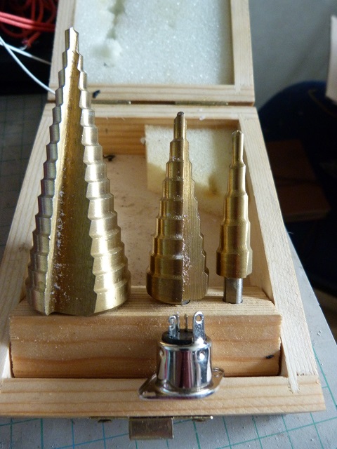
Mine doesn’t come with screw locking but is just a push fit.
It also has a connector shell size of 13mm, this didn’t fit into the hole.
I have a set of (#amazon link)step drills – very handy for jobs like this where you need to increase the hole size.
I selected the one which would give the right size hole and marked it with tape to prevent overdrilling.
As the frame is made from acrylic, known to be fairly brittle, I put the drill bit into a battery drill to keep the speed down.
Taking it slowly and hardly pushing the drill into the hole, it cut 
You can tell when you are overheating the acrylic, this is when you stop getting swarf coming out.
At this point stop the drill, clean it off, get all of the melted plastic off and promise yourself that you won’t spin the drill that fast.
I found that the correct drill size was going to become one size up before cutting right through, so you will need access to both sides of the frame.
As it was I had to remove the screws from the power supply before I started, as the drill was going to be drilling into this.
Once the center hole is big enough for the connector to fit, I held it in position to drill one of the securing holes.
A 3mm drill bit went through the hole – so was used to start the hole.
Removing the connector, I upped the drill bit to 3.5mm, allowing for tolerance on a m3 screw and slop for hand drilling.
Don’t do what I did on the first hole, which is to drill all the way through with the 3mm bit and then try the 3.5mm – I could feel it trying to catch and chip, almost breaking the acrylic frame piece.
Fit the connector back and push a screw through the first hole to locate where the second hole should be drilled, and using the same technique of starting with a 3mm nd moving up to a 3.5mm , drill the second hole.
With hind sight – you maybe able to fit the connector behind the acrylic frame, only drilling two mounting holes to secure it. This will need to be tested for connector security as you may not be able to push the tool connector home fully.
Wiring up the connector
I chose a (#amazon link) 5 way din connector.
This gives us options for interconnects.
We can add intelligence behind the frame or we can design tools with intelligence.
With a 5 way connector you also get the outer shell of the connector, so you do have 6 ways to connect.
The first connection was the 12v.
We need two wires and I chose the outer two pins as the 12v feed and 12v return.
This will be connected straight to the power supply and will always be on.
A future mod may be a switch to isolate this connector.
A thought for the other wires is to use a pair as temperature feedback, with the last pin as a digital input.
So all of the pins were wired up prior to final fitting.
A heavy ish pair of wires for the 12v fee and return, terminated the other end in fork crimps to be fitted to the power supply.
Lighter wires have been used for the other four wires , including the shell of the connector.
These have been tucked away behind the frame and taped so that they will not interfere with the power supply.
Fit the wires to the power supply terminals before refitting the power supply to the frame.
Then fit the auxilliary socket, bending the wires and making sure nothing is going to short out- it is probably preferable to cover the soldered connections with heatshrink to prevent shorting, but make sure they are not too long so as to interfere with the fitting of the power supply.
As I said before, tape up the unused wires and tuck them out of the way.
Make sure you create a diagram of the wiring, in 6 months when you design a superb new bit of kit, which blows up if connected the wrong way round, you will be fiddling about checking which pins the voltage is on.
When creating a diagram, make sure to show whether it is from the front or rear of the connector.
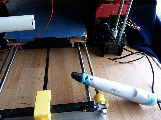
At present, all I have to connect to the (#amazon link)aux socket is a 3d pen and this works well.


I am trying a 12v soldering iron to see if I can connect it to the socket, but have not tried this yet.
A 12v light can be made easily from an empty pen – or even printed, with a clip to secure it onto the frame and position it where you want light for maintenance or other tasks.
I am limiting the power drawn to 60w as I am still using the original power supply – with a 350w as a backup still in its box!
So there you go, now you have an auxilliary socket on your Anet A8, what are you going to plug into yours?
If you have a tool that you know will be useful to plug into your new 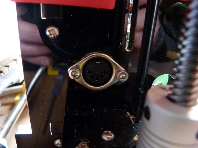
So here’s a picture of the Anet A8 mods, the auxilliary connector fitted.
Thanks for reading
Phil