Thanks to GearBest my order of spare main boards was delayed until a few days ago, and my printer is normally on the go – so I didn’t want to strip it down.
So the first thing I did was to run a new main board up with a power supply – to test it.
I was under the impression that you could run the whole board off the usb, same as the mega. But this is not the case you need power to the board from the 12v dc input.
Now getting the computer to recognise the board was easy – with the ch340 driver installed.
Connecting through the serial port at 115k baud the computer recognised the board in pronterface , but the ‘printer’ was not working – it had errors.
You need to connect the two thermisters, one for the bed and the other for the hotend before you can fool the board into thinking it is a working printer.
So with these now connected, I was able to switch on and off the bed with pronterface.
Switching it all off and now connecting the external mosfet as I had described in an earlier post.
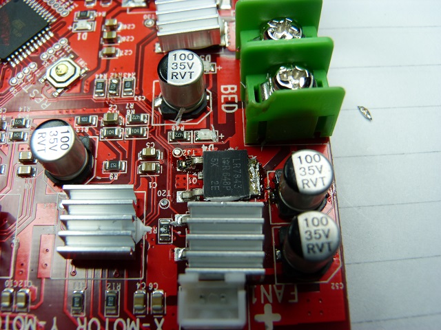
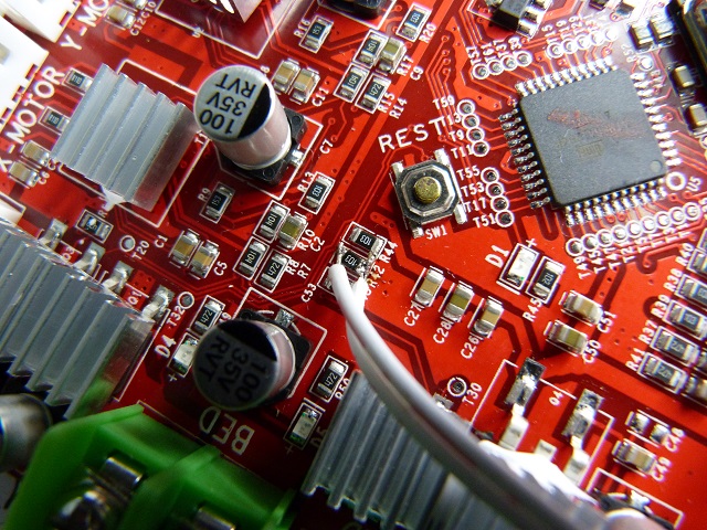
Connect the control wires across r42, the gate resistor for Q1 the bed mosfet.
First thing I had to do was find r42, the second was to solder wires either side of it.
Being an 0805 surface mount resistor you don’t have much space between the pads of the resistor, but it is possible to solder either side of it.
Note: an easier place to connect the wires is across the bed mosfet – the two legs are the same terminals as the resistor and wider spaced.
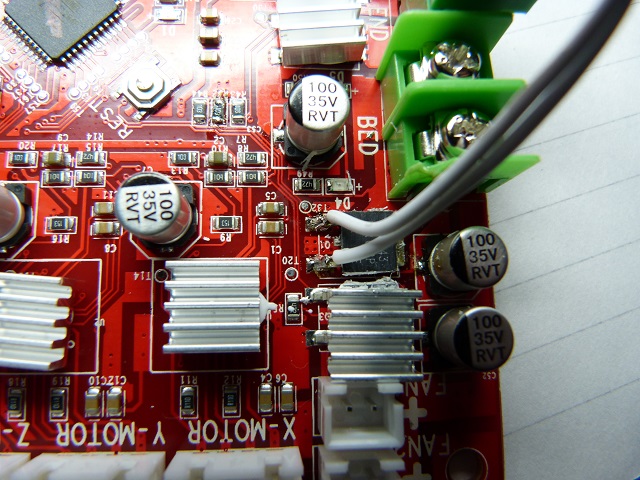
Wiring in the supply to the mosfet board and putting a load on it of a car led indicator lamp – closest thing I had to hand which worked at 12v easily!, I switched it all back on.
Reconnecting the computer I switched the bed on and … nothing- no light – the onboard mosefet switched on but not the external one.
Ok so what is wrong.
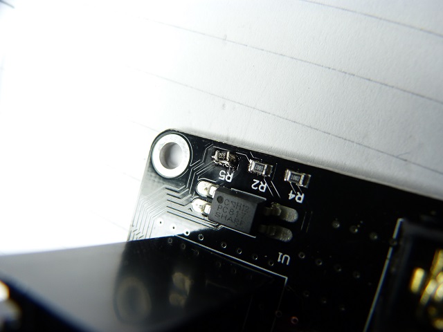
Looking at the circuit, the control voltage goes through a full bridge – to make it polarity independent.
This will take 0.6v off either pin – so from the 5v controller output you need to subtract 1.2v – we are left with 3.6v.
This is fed through a 10k resistor (R5) to the opto device to pass current through a led – this in turn switches on the opto transistor, eventually switching on the output mosfet.
The point of this is, that with 12v on the control input there is enough current through the led to activate the device, but with 5v there isn’t.
Damn – what now!
Calculating the current through the 10k resistor with 12v ( (12-1.2- 1)/10k= 1mA) and with the 5v input ((5-1.2-1)/10k= 0.3mA) we can see why the opto switch is not working.
Note the extra 1v drop in the above equation is for the led internal to the opto device.
So working it the other way round – we need a minimum of 1mA to operate the opto device we can use the voltage to calculate the resistor value.
5-1.2-1 = 2.8v
To have 1mA flowing and calculate the resistor value we divide the voltage by the current.
2.8/0.001 = 2800 or 2k7
I am very lucky to have an 0805 resistor kit, so I looked through this and found the closest value was 2k7 (preferred value). Removing the fitted one and replacing it with the 2k7, reconnecting and switching the bed on and off it worked.
So if your anet a8 main board has blown its bed mosfet you have three choices.
Replace the Bed mosfet(ebay link)– see below for directions on how to do this easily.
Use the controller voltage but change the resistor value on the external mosfet board.(#amazon link) resistor kit
Replacing the onboard mosfet easily.
Note: remember these devices are static sensitive – pick up the device and then touch the board with a finger to get both the board and device to te same potential- reducing the chance of it blowing up!
I have just been reminded that you need to know the device number to replace it! The device is an IRLR7843 mosfet.
Can be obtained ebay sources in the UK or elsewhere dependant on time scales.
The onboard bed mosfet is located where the designator says Q1. It is under the silver heatsink.
This heatsink is held in place with thermal silicon adhesive.
To remove this heatsink, take a flat screwdriver and carefully lever the heatsink away from the device. This may pop off easily or be very difficult. If you use the board as a lever by the green connectors it is controllable – but be careful you don’t damage the board.
Once this is off you can see the device is held down to the board with two legs and the back pad.
To remove this device easily – carefully cut the legs of the device close to the package.
Use a soldering iron to remove the cut legs- don’t damage the pads on the board.
To remove the main body, hold the tip of the soldering iron against the metal tab at the top of the device and feed a bit of solder onto the iron.
You will see the solder flow onto the tab of the device – when this happens it is ready to be removed.
Use a pair of tweezers to lift the device off the large rear pad and you have done it – congratulations.
All you have to do is to clean up the large pad – make the solder flat – and replace the device with a new one.
To remove the solder from the pad I use (#amazon link) solder wick.
To use this lay the solder wick over the solder you want to remove and press on top of this with the soldering iron, you will see the solder melt and flow into the solder wick.
Remove the solder wick from the area before the solder solidifies.
If the solder solidifies then remelt the solder with the soldering iron and remove it quicker.
Remember that this wick is copper and it will conduct heat – so keep your fingers a little away from where you are going to remove the solder. Or get asbestos fingers!
To replace the device
Melt a little solder onto the large pad. And I mean a little.
Place the device onto the pad and heat the tab.
Feed a little solder onto the iron while it is in contact with the tab and the large pad to assist reflow.
When the solder melts then position the device carefully with tweezers – making sure the two legs are on the correct pads, remove the iron.
Solder the two remaiming legs to their respective pads.
Now all you have to do is to glue the heatsink back on with this (#amazon link)thermal compound.
And you are done.
Now test the board – without loading it with the bed to start with.
So there you have it – how to replace your bed mosfet and how to wire in an external mosfet if your anet a8 bed mosfet blows!
It sounds complicated but really isn’t.
If you have a go at replacing your Anet A8 bed mosfet and have problems then why not comment in the box below and we can try to sort the problem out.
going to have a go at this, the temp on hotbed constantly reads 148 and checked the thermistor is working perfect so thats not the issue. Pryed the heatsink off and the top cover of the mosfet came off with it, dont think that should be an issue though so going to try and get it off the board tomorrow
Great Aaron, I wish you the best of luck with replacing your mosfet. I think this is the main advantage over the ready made printers, we are prepared to have a go at fixing it rather than throwing it away or being scared of getting into the nuts and bolts. Let me know how it goes. Phil
Do You know if the hot end mosfet is the same as the heated bed mosfet ?
from what i remember both those mosfets are hte same James… just checked a board and yes they are… I take it yours has blown
My anet a8 hotend fail to heat up. Heater for hotend confirm to be working fine. When I remove the hotend heater cable from the board, there is output voltage supply to the hotend heater when turn on extruder heating. If i plug back the hotend heater, the output of the board fail to deliver 12vdc to the hotend heater during turn on extruder heating. Could it be the mosfet (under the heatsink) for hotend is fail causing the problem? Appreciate for yr feedback.
Hey Stuart… if you have tested the resistance of the heater and that is fine then that should be ok…. the circuit is a 12v feed and the mosfet is on the return path…. so you should get 12v at the mosfet end of the heater when it is off… when the heater is on then you get low volts ( close to 0v) at the mosfet end with 12v on the feed side to the heater… with the output of the board failing to delvier the 12v i would be looking at the current limit prior to the output… what happens if you take a seperate feed and supply the heater with 12v and switch on the heater…does it work… if so then it is between the 12v input and the feed for the heater ( suspect connector joint or inline fuse) let me know what you find Phil
Right now, I connect the output of the board (12vdc) into coil of external ssr. Then, the hotend heater is connect to external ssr. It works… However, it’ll be danger in term of safety. If one day the ssr become faulty and get into normally close, the hotend heater will continually turn on eventhrough the printer thermistor is detecting over temperature. I think I’m going to get external 3d printer mosfet connect to both heater bed and hotend for safety.
Both ssr’s and mosfets can fail in the closed stateleading to constant heating… always a danger… even a mechanical relay is not immune to failing shut… i have had this with an arc as the relay shut… so if you want more reliability for failure cases it maybe worth adding an inline thermal fuse touching the hotend… it can be added to the existing wiring by adding it inline with one of the wires…you will need to use high temp wire to prevent damage to the insulation…aliexpress are quoting fuses that blow at 300c and hold at 285 …so for most filaments should be ok…. and the current for the bed may be a problem for the lower temperature devices….but the bed will not get above 120c even fully on so poses less of a fire risk than the hotend… i would definitely go with the external mosfets…
Thanks Phil for your details explaination. The external mosfets is controlling both hotend +12v and 0v at the same time. I guess it’s very unlikely that both mosfet will fail at the same time and reflect to close state leading and create constant hearing dangerous.
i reckon that would be true…unlikely to both fail… this is all i have on my printer and not had a problem so far…


going to have a go at this, the temp on hotbed constantly reads 148 and checked the thermistor is working perfect so thats not the issue. Pryed the heatsink off and the top cover of the mosfet came off with it, dont think that should be an issue though so going to try and get it off the board tomorrow
Great Aaron, I wish you the best of luck with replacing your mosfet.
I think this is the main advantage over the ready made printers, we are prepared to have a go at fixing it rather than throwing it away or being scared of getting into the nuts and bolts.
Let me know how it goes.
Phil
Do You know if the hot end mosfet is the same as the heated bed mosfet ?
from what i remember both those mosfets are hte same James…
just checked a board and yes they are…
I take it yours has blown
My anet a8 hotend fail to heat up.
Heater for hotend confirm to be working fine.
When I remove the hotend heater cable from the board, there is output voltage supply to the hotend heater when turn on extruder heating.
If i plug back the hotend heater, the output of the board fail to deliver 12vdc to the hotend heater during turn on extruder heating.
Could it be the mosfet (under the heatsink) for hotend is fail causing the problem?
Appreciate for yr feedback.
Hey Stuart…
if you have tested the resistance of the heater and that is fine then that should be ok….
the circuit is a 12v feed and the mosfet is on the return path….
so you should get 12v at the mosfet end of the heater when it is off…
when the heater is on then you get low volts ( close to 0v) at the mosfet end with 12v on the feed side to the heater…
with the output of the board failing to delvier the 12v i would be looking at the current limit prior to the output…
what happens if you take a seperate feed and supply the heater with 12v and switch on the heater…does it work…
if so then it is between the 12v input and the feed for the heater ( suspect connector joint or inline fuse)
let me know what you find
Phil
Right now, I connect the output of the board (12vdc) into coil of external ssr.
Then, the hotend heater is connect to external ssr.
It works…
However, it’ll be danger in term of safety. If one day the ssr become faulty and get into normally close, the hotend heater will continually turn on eventhrough the printer thermistor is detecting over temperature.
I think I’m going to get external 3d printer mosfet connect to both heater bed and hotend for safety.
Both ssr’s and mosfets can fail in the closed stateleading to constant heating… always a danger…
even a mechanical relay is not immune to failing shut… i have had this with an arc as the relay shut…
so if you want more reliability for failure cases it maybe worth adding an inline thermal fuse touching the hotend…
it can be added to the existing wiring by adding it inline with one of the wires…you will need to use high temp wire to prevent damage to the insulation…aliexpress are quoting fuses that blow at 300c and hold at 285 …so for most filaments should be ok….
and the current for the bed may be a problem for the lower temperature devices….but the bed will not get above 120c even fully on so poses less of a fire risk than the hotend…
i would definitely go with the external mosfets…
Thanks Phil for your details explaination.
The external mosfets is controlling both hotend +12v and 0v at the same time.
I guess it’s very unlikely that both mosfet will fail at the same time and reflect to close state leading and create constant hearing dangerous.
i reckon that would be true…unlikely to both fail…
this is all i have on my printer and not had a problem so far…