

A lot of people are interested in the Anet A8 upgrades, especially the mosfet mod for the heated bed.
The reason for this is a lot of misinformation out on the web about the mosfet on the main board being too small and causing fires.
If you really want to carry out this mod then follow the directions in this post.
We will go through everything you need to do to carry this procedure out safely.
When your main board has broken
If your mosfet has broken and you are trying to repair the board with an external mosfet follow the procedure and take into account the last section on the blown onboard mosfet. This will show you where to take the activation feed from if there is nothing from the mosfet output.
UPDATE: I found that there is a problem with this – read my post on what to do <here >
Tools for the Anet a8 upgrades
To carry out this modification with a working board you will need the following tools
(#amazon links)
screwdrivers to suit screws on motherboard and mosfet board
crimp tool – manual or automatic
Control cable ( normally supplied with mosfet board)
wire – two colours preferably red and black but mains cable will do
insulated fork crimp terminals – 6 off with 4mm spade or 5mm
M3 x 20mm or longer – to secure the mosfet board
M3 nut
Procedure
Switch off the printer.
Disconnect from the mains.
Switch the printer on, to discharge any residual power.
Unscrew the two wires from the heated bed connector on the motherboard.
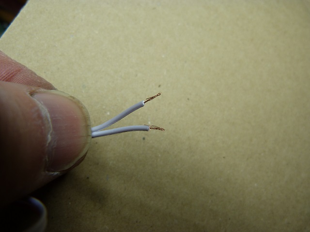
If not fitted crimp fork terminals onto wire ends.
Prepare two pieces of wire – different colours
I used a spare piece of mains cable – 13A.
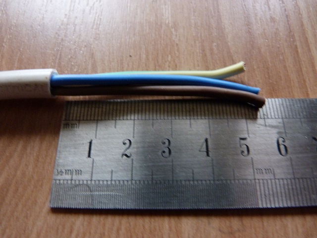
Using the brown as the live(12v) and the blue as the neutral(ground).
In hindsight what I should have used is the green as the ground.
So I stripped back 50mm of outer insulation to expose the three wires.
I stripped 6mm back on two wires.
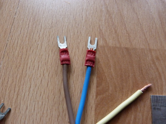
Crimp a fork terminal on each wire.
Get access to the power supply bottom, where the mains and dc supply are.
Unscrew one negative and one positive terminal.
Push the fork terminals onto the correct places.
Brown for the positive and blue for the negative.
Tighten the screws.
Feed the wires through the access holes for the wires and route across the bottom of the printer.
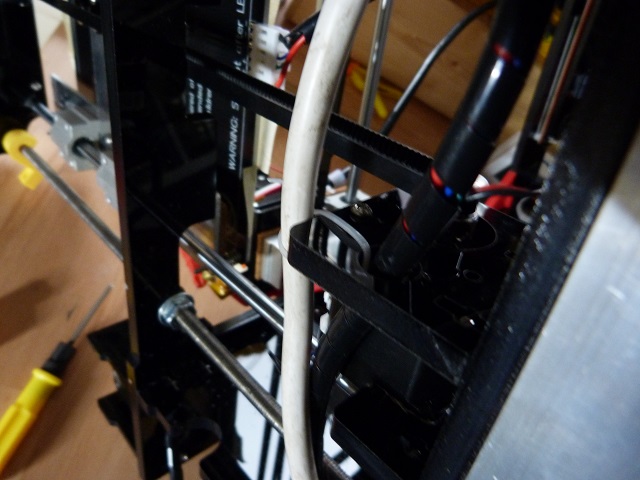
Ensure that the new wiring does not interfere with any existing wiring or mechanical structure .
What I did was to cable tie the cable to the motor mount for security.
Feed the cable through the other side where the mother board is located.
Reassemble any covers which have been disturbed.

As you can see on mine I have the mains socket mod, I needed to reassemble this with the two screws at the rear.
Place the printer upright and have the mother board area facing you.
Unscrew the two wires from the bed connector on the motherboard.
Strip 6mm of insulation from the unterminated ends of the control cable.
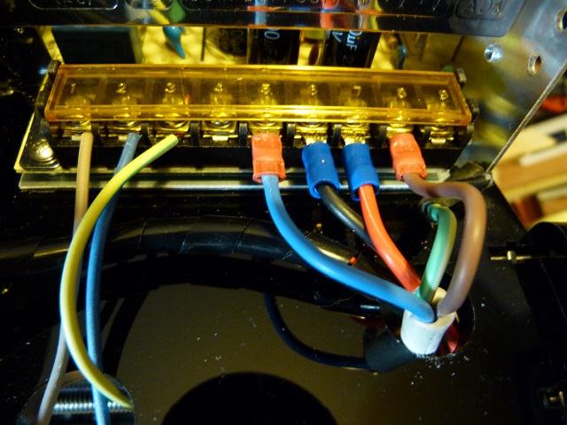
Screw these into the connectors on the motherboard.
It doesn’t matter which way round these are connected – the mosfet board takes care of the voltage.
Fit and crimp two fork crimps onto the bed cables – if not already fitted.
Hold the mosfet board in its final position.
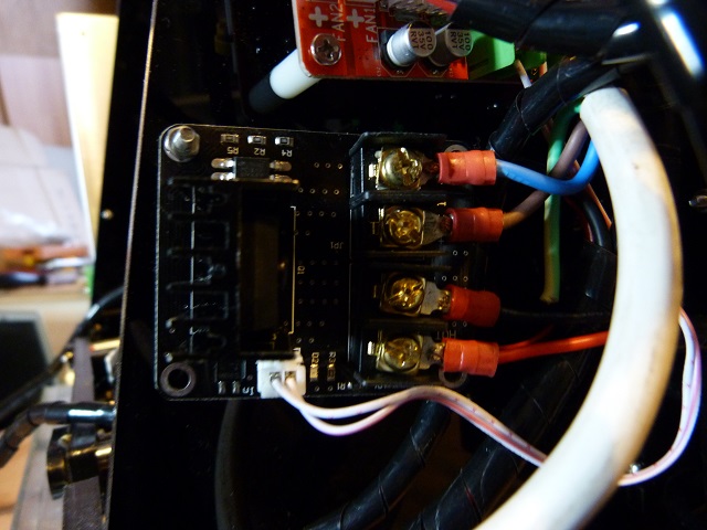
I found that there is a screw hole just under the motherboard towards the edge, and used that as a pickup for one of the mounting holes on the mosfet board.
For the new dc cable from the power supply to the location of the mosfet board and allow another 50mm.
Trim the length.
Strip back 50mm of outer insulation to expose the cables.
Strip back 5mm of cable insulation to expose the copper conductor.
Crimp a fork terminal connector onto each wire.
Unscrew the positive and negative dc connections on the mosfet board.
Fit the brown connection into the positive connetion and secure.
Fit the blue connection into the negative connection and secure.
Unscrew the two mosfet connections on the mosfet board.
Fit and secure the red connection from the bed to the outer connection on the mosfet board.
Fit and secure the black connection from the bed to the correct connection on the mosfet board.
Locate and secure the mosfet board in its final location, using a screw and nut.
Plug in the control connector into the mosfet board.
The installation is now complete.
Testing the anet A8 upgrades
To test the correct operation of the mosfet board you will need to plug in the mains.
It will be a visual inspection to see the correct operation so no test equipment is required.
Make sure any wiring is not trapped or will get trapped when the bed is moved.
On mine as I had added a cable, the wires for the y axis motor had moved up and would have caught on the lower plate probably damaging them if I had not carried out a manual movement first – so always worth doing.
Switch on the mains and listen for any unusual noises or smells or smoke, if there is some switch off immediately.
As your printer sound normal and the display is the correct startup one.
Observe that there is a red light lit on the mosfet board – indicating the supply voltage is present.
Navigate to the extruder menu.
Scroll down to the bed temp setting and set the bed to 30C.
Observe that the light on the bed has illuminated.
Observe that a light has lit on the mosfet board.
On mine this was a blue light, but may be a different colour on other boards.
Observe that the display shows the bed heating.
Feel that the bed is getting warm.
When the temperature reaches the target observe that the light on the bed goes out.
Observe that the light on the mosfet board goes out.
You now have a working mosfet upgrade board.
Happy printing.
What should I do if it doesn’t
no red light on the mosfet board with the printer switched on.
Check the connections from the power supply to the mosfet board are correct .
Positive to positive and negative to negative.
Use a multimeter to ensure the crimps have been done correctly, 12 v present on the mosfet board.
If this is present the led diode or resistor may not be soldered correctly.
My heater comes on when I switch the printer on.
Check the polarity of the supply input and rectify if incorrect.
Check for 12v on the mosfet pins.
Check for control light lit – if lit 12v being supplied to board.
Switch off printer, disconnect the control connector and switch printer on.
If this has cleared the heater on at switch on then the mosfet on the main may have gone short circuit.
No control light when the bed should heat up
check the voltage across the control connector when the bed should be heating.
If it is not 12v then check the wires and not the insulation has been connected on the motherboard.
Check for 12v across the two connections on the motherboard when the bed should be heating.
No 12v when the bed should be heating.
This means that either the mosfet on the motherboard is faulty or the controller chip is faulty.
Using a multimeter find pest point T31 and place the positive probe on there and the negative probe on ground or the source of the Mosfet.
Be careful not to short anything out.
When the bed is supposed to be heating this voltage will go to 5v.
When the bed is not heating this will be 0v.
If this is correct and the output is not then the mosfet is faulty.
To drive the external mosfet board you will need to pick up on this 5v change on T31 or T32.
Solder one wire to this point – be careful not to short anything else out.
Solder the other to ground ( you can use the ground connection on the Mosfet for convenience.
Your external mosfet board should now work.
With the directions here and the fault finding at the end you should have a working printer again, if you have any problems relating to this please contact me either directly or in the contact box below.
There are more Anet A8 upgrades, to come so why not sign up to be notified when I post them.
Thanks for reading
Phil