
Adding a mains socket to the anet a8 power supply
The anet a8 is powered from the mains.

The supplied kit has a mains lead which is connected to the anet a8 power supply directly.
To switch on and off the printer involves pulling the plug.
If the printer starts going wrong and you need to stop it quickly, then pulling the plug may be the only option – can you reach yours quickly?
If not there is a mod you can do easily to add a mains switch and socket.
This mod makes it easy to move the printer around, with out the cable trailing and allows the printer to be switched on and off when stood in front of it.
So would you like to see how easy it is and what is involved? Of course you would.
Parts Required
To start we need to get some parts together.
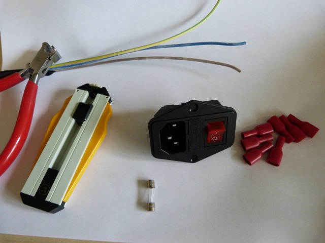
These are : (#amazon links)

mains socket with switch and fuse holder
6.3mm crimp sockets (7 off)
wire cutters
wire
- fuse 20mm 3.15A 250v – pack!
The mains socket with switch and fuse holder I bought from china via aliexpress.
If you want one quicker than 2 months rather than risk the chance of breakages on the way ( I bought 5 , one broke and 3 were crushed!) then I would suggest Amazon.
The crimps also came from china, aliexpress again and similarly can be got from Amazon.
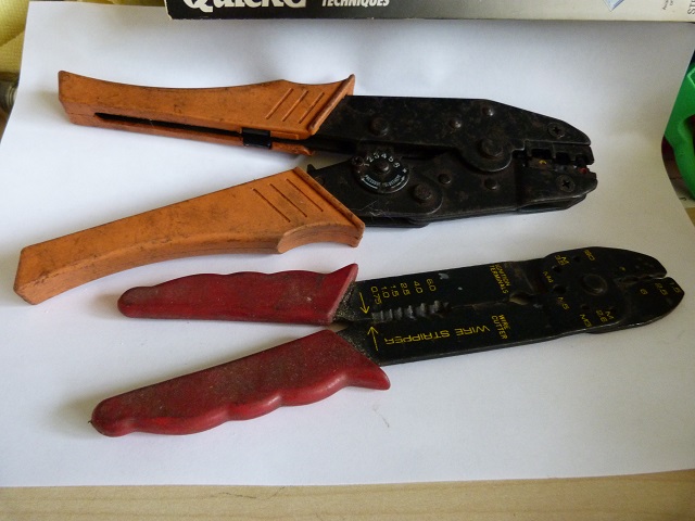
The wire strippers, this set are designed to cut the insulation all around the cable, Some wire – particularly PTFE insulation will not break easily and needs cutting all around the cable. So this set has a pair of ‘v’ cutters which cut the insulation all around the cable. These can be obtained from Amazon.
The wire cutters, in this case are end trimmers, and you can use the pair supplied with the Anet A8 kit, if they are still in one piece!
The crimp tool comes in two varieties, a manual one and an automatic one. Which one is best? Well as I crimp a fair bit I splashed out and purchased the (#amazon link) automatic pair, but for years before that I managed with the manual pair.
You need to be a little careful when crimping the wires with the manual pair, but it does come with wire strippers and a wire cutter as well on the tool.
The wire – you can use the mains cable which was supplied with the kit. You will need to buy a kettle lead, IEC lead, but these are very common, again Amazon have them.
The procedure to modify the anet a8 power supply
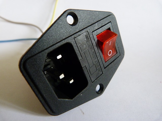
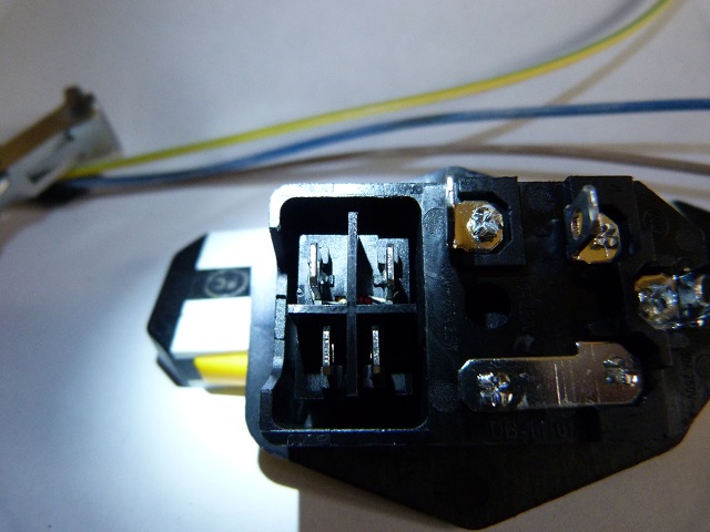
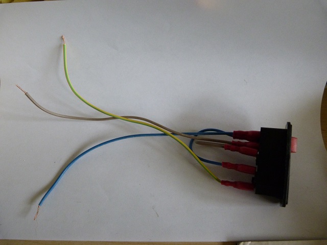
Take a look at the mains connector with switch and you will see two distinct parts.
One the mains connector, with three connections, and the switch with four connections.
Lets deal with the mains socket first.
The three connections are : live , neutral and earth.
A little tip I learnt is to hold a plug with the back off and the three pins show the earth at the top, with the BRown in the Bottom Right for live, and the BLue in the Bottom Left for neutral.
With the fused IEC connector you have the earth in the top, with the neutral coming straight off the pin, but the live goes through the fuse before coming out to the terminal pin. So the live pin will be in an offset place and maybe under the neutral.
Preparing the wire
Strip back the outer sheath of the mains cable to expose the three wires. You need to strip back 300mm (12”) at least.
Cut the three wires off.
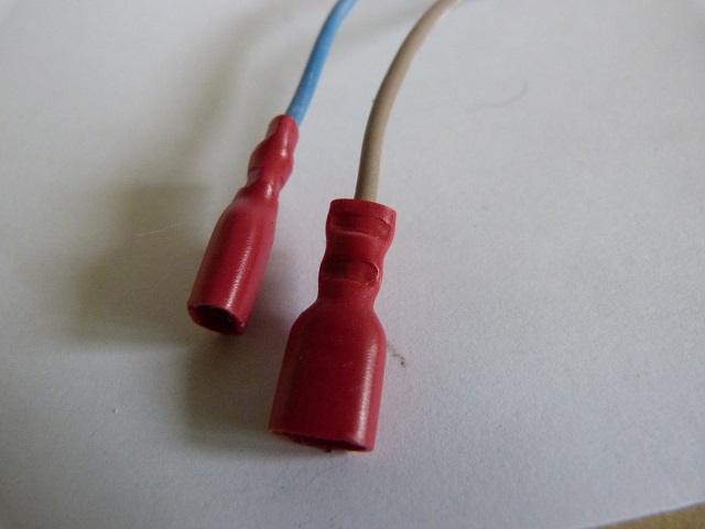
Set the wire strippers to remove 5mm of insulation, the reason for this length is the crimp has a barrel inside to take 5mm of stripped wire, see the stripped down insulated crimp for how it is constructed.
Push the wire into the back of the crimp and the insulation will butt up against a stop.
Insert these into the crimp tool and with the manual one crimp the ferrule – close to the wider apart, then the back to secure the insulation.
With the automatic crimp tool – ensure you put it in the right way round and then compress the handles until you hear a little click and the ratchet mechanism will release. There will be numbers stamped onto the crimp to assist, in industry, with quality – you know the right tool has been used.
You need to terminate the ends of all three wires, so go ahead and crimp the other two.
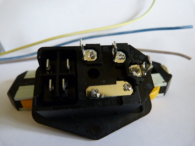
Connecting to the input connector
As stated above, the earth goes on the top connector.
With the blue going onto the other connector at the left of the input connector.
The live ( brown) goes onto the connector below this – at the output side of the fuse.
This means that if there is a problem with the printer the fuse will blow, protecting you from an overheating machine.
Wiring up the switch
The switch input is going to be wired up next.
If you look at the four switch contacts, if you have the illuminated switch version, two of the contacts will have very thin wires already connected to them, these are the neon included within the switch to show that it is on.
These two contacts are the output – or go to the power supply of the printer.
It is the other two which we are interested in at the moment.
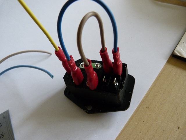
So taking the blue wire attached to the input connector you want to loop it around to one of the contacts, the loop wants to be about 3” (75mm ) tall.
This loop will allow you to strip back and crimp on another crimp, then have enough wire to easily push the crimp on.
So go ahead and loop the blue around with a 3” loop, hold your fingers where this is and use the cutters to trim the wire.
Strip 5mm of insulation and crimp a crimp onto the end of the wire.
Now with the switch I had fitted the input terminals were closer to the middle separator, so I had to ensure that the crimp long side of the metal piece was fitted towards the middle.
Go ahead and do the same with the live ( brown) wire, cut, crimp and push it onto the other connector next to the one with the blue wire on.
Wires to the power supply
Now we need to be able to connect to the power supply.
The two wires cut off , brown and blue are stripped and have crimps crimped onto one end.
The other end is stripped of insulation about 15mm .
The earth wire free end is also stripped by 15mm.
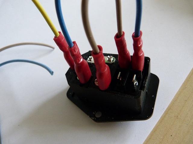
Assembling the power supply connector cover
The mains connector switch assembly is now fitted into the power supply connector cover.
The two screws are fitted and the correct nuts are secured on the back.
The length of wires should be long enough to allow fitment to the power supply.
I had to lay my printer on one side to screw them into place easily.
Fit a screw into the rear of the cover assembly to secure it.
I used a bit of mastic – silicone sealant to secure the front as my print had warped a bit – I took it off the printer too quickly without letting it cool down properly!!
Final check
Put the printer upright on it’s base board – you have got one haven’t you!.
Try to move the input switch assembly, hopefully it is secured.
Plug in an IEC mains lead – kettle lead.
Ensure the switch is in the off position.
Plug in the IEC lead and switch on.
Note – when doing this it is always a good idea to keep your finger on the switch, to be able to switch off if anything unusual occurs. So when switching on – tense yourself – so if there is a bang or noise the n you will jump less and be prepared to switch off quickly.
Will this prevent damage- probably not but it is reassuring to know you can now switch off your printer.
When the switch is in the on position the light should be illuminated to show that the switch is in the on position.
Others say that the connections should be the other way round to show mains is present, and the mere fact that the screen is lit shows that the printer is on.
Your choice.

Ah you got me – i forgot to tell you about the fuse! sorry.
You may have already fitted yours, but if not then here goes.
The fuse holder may have fallen out when you were wiring up your connector.
if you look down the hole it was in you will see where the fuse goes, but don’t shove it down there – you will never get it out.
That is what the piece which fell out helps with.
Fit a fuse as shown in the clip, if you have a spare fuse then you can load it up in the hole above that.
Now making sure you have it the right way round ( with the tab towards the mains socket hole), push it down until it is flush.
Hopefully it went in with a littl click and is now not able to fall out. good.
What if i need to change the fuse?
Well if there is a problem and the fuse does blow you will need to take out the clip you just nserted.
You will need to remove the mains lead and where that aperture is there is a little gap.
You will need a small screwdriver to fit into this gap and be used as a lever.
Once inserted into the gap, you can use the other side of the mains socket as a point of lever and the clip should pop up a bit, releasing the clip.
Remember that spare fuse you stored in the clip, well you don’t have a spare any more – so you need to get some more.
Just pull out the original fuse and replace it with the spare.
If you have some more then always replace the spare – just in case!
Now push the clip back into the holder and it is ready for you to try again. Plug in the mains lead and away you go again.
Well I hope you have made it this far and have now got yor printer
Well I hope you have followed carefully this tutorial on adding a mains switch to your anet a8 power supply and can now switch on and off while standing in front of it.
Thanks for reading
Phil
Thank you for this helpful post. It works perfectly !
Brilliant – thanks for stopping by Paul.
Glad to have been helpful.
Is there anything else you want to mod on your printer that i haven’t covered yet?
Hello Phil,
My next steps are upgrading hotend and extruder with adding a BL touch. I can handle it! Your other mods are really helpful too.
But what I don’t find nowhere is how to add leds and wiring it (I don’t know anything in electricity). Maybe you have already done this kind of job ;)
I have upgraded my hotend to an allmetal one with silent fans – i have the bltouch clone but not installed it yet- but i am glad you are finding the info helpful.
i thought i had done an article – just found it https://best3dprinter.stan-tech.com/anet-a8-upgrades-adding-led-light-to-see-your-prints – the leds are run off the main 12v – they are useful.
just make sure that the psu can handle it – although this many is such a light load.
when using the all metal to prevent jams allow your printer to cool all the way down below 40C before switching off.
i am thinking of adding a raspberry pi and modifying the code to auto switch off when the hotend is cool enough.
but as with most things, haven’t had the time to continue with the printing.
Good luck with your mods – please shout if you want to know anything.
Are you using a standard board for the bl touch integration? are you ok with soldering?