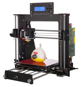
A reader has Kindly generated an article to help you with your CTC printer problems.
I will let you read it in his words….
by Ray J, Hereford, UK.
At the start
Purchased a the CTC printer through Amazon, and arrived within 3 days.
First impressions
It is a very cost effective 3d printer, possibly not for someone who thinks that it will produce good results straight away.
The Menu system is clunky (with switch press model).
Followed build instructions on the supplied CD and youtube link supplied with the kit.
Modifications performed
Power Socket
Supplied un-switched power socket replaced with switched variant so that if things went wrong I could cut the power straight away.
This was mounted in a ABS box so that there was no exposed main power lines.
Bed Mounting
First major issue was that the y-axis bed (bottom rails) were not mounted rigidly to the z-axis upright.
This could cause everything to float when moving the printer.
First solution
My first solution was to print some U-shaped brackets to mount over the
bottom bars and screwed to a solid board. This worked to certain extent,
but the frame could still move about the centre upright.
I look for another solution.
Second solution
This involved purchasing a 1 metre length of M8 all-thread from B&Q, along with 12 OFF M8 nuts, and designing a clamp to grip the centre upright.
The clamp was printed first with the original fixing method used, so that the printer could be stripped to perform the rest of the modification.
The two bottom bars were removed from the end plates, and where these had been fitted 8mm holes were drilled through to allow the all-thread to pass through.
The all-thread was then cut to two lengths 440mm long, this allowed for the nuts to be fitted both sides of the end plates.
The all-thread was fitted starting from the back plate (bolted firmly), then the centre section with the clamp (M3 screws and nuts using the original plate holes bolted firmly with M8 nuts on the all-thread), and finally bolted firmly to the front plate.
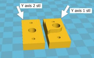

This solution made the whole printer base more rigid and did not require the printer having to be bolted to a solid board.
STL file – Y axis support 1.stl and Y axis support 2.stl
editors note : see end of post for stl download
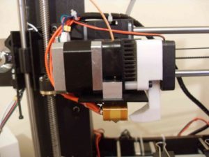
Extruder Ducting:
With the PLA supplied with the printer my prints were very messy due to the material remaining hot.
Found a cooling duct on thingiverse that could use the existing fan
(didn’t require another fan).

Z-axis Top Support
When first tensioning the X-axis belt I noticed that the z-axis screws were being pulled in on the top mounts, and could cause wear grooves in the top mount.
Designing a top mount support with a bearing for the z-axis screws and grub screw to fix into the z-axis slide.
Two extra M3 mounting were added and required drilling the existing top mount to take the M3 screws and nuts.
Results were a little better but not much, and were not improved by
using flexible couplers, from the motors to the z-axis screws.
Amazon 698-2rs bearing – 19mm Outer diameter, 8mm Bore – 6mm wide High Carbon Steel (10pcs)


Lefthand STL file – Mk1 LeftHand Z support.stl
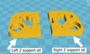

Righthand STL file – Mk1 RightHand Z support.stl
editors note : see end of post for download
Belt Tensioner:
My next observation was black plastic dust on top of the right z-axis
motor, and behind the front plate centre.
On closer investigation the plastic dust was from the idler pulley frames.
The centre bar that the pulley is attached to is D-shaped, therefore when tension is applied to the belt the flat of the D-shape eats at the plastic frame when rotated, and wears a slot.
This was also noticed at the end of medium print as the belts were not the same tension from the start of the print.
My solution was to redesign the idler frame to take the same D-shaped bar but have it mounted into bearings either side. When swapping with the existing frame note the orientation of the original frame.
Results were that the belts retained the same tension throughout the print.
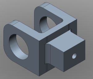

This image is of the belt tensioner drawn in Autodesk 123D Beta.
Bearings fitted
Amazon – 605zz – 14mm Outer diameter, 5mm Bore – 5mm wide High Carbon Steel
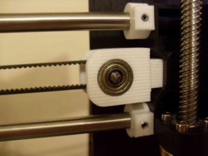

STL file – Belt Tension with Bearing.stl
editors note : see end of post for download
The following modifications were made due to excessive Z-banding on
the prints.
Motor and Idler pulleys:
Machined aluminium geared pulleys were purchased from Amazon to reduce / remove backlash when motors / idlers changed direction. These items are secured using two grub screws.
Amazon.co.uk – Balitensen BAL-S2M17T5B6W-2 – S2M Pulley 17 teeth 5mm Bore – 6mm wide 3D printer part – (uk only…)
editors note – 17 tooth is not a usual pulley 16 or 20 tooth are more common – you will need to adjust the steps per mm – but the closest is the (#ad) 16 tooth from Amazon
Bed Belt Mounting:
The standoff on the bed was done by the use of stacked wooden spacers that were not quite the right height so that y-axis belt did not run parallel. A standoff was designed to give the correct height with loops fitted for securing the belts.


STL file – Y axis belt mount.stl
editors note : see end of post for download
Z-axis Screws:
The z-axis screws were replaced due to high amount of visible runout that could be seen with naked eye.
Alternative parts were sourced from Amazon along with a dial gauge indicator and stand for fine tuning the mechanical setup.
Amazon – HAWKUNG HK-221 – 300mm 8mm T8-2 Stainless Steel threaded rod lead screws with T8 nuts (2pcs)
Amazon- Flexible shaft coupling 5mm to 8mm (5pcs)
editors note : (#ad) dti and stand for fine tuning
Marlin Update:
NOTE: Read these instructions fully and understand before applying to the 3D printer.
With the modified threaded rod the printer would now move 10mm for a 1mm setting on the printer.
Thinking that I could change the stepper motor step setting and store them in the EEPROM on the controller board proved fruitless, as the EEPROM on the controller was not enabled.
(editors Note : this can be done even with the EEPROM disabled as you can add it to the slicer start up setting for each model – but it does have the disadvantage of not being set in the machine…)
This led to the only conclusion that the controller had to be updated to the Marlin firmware.
editor: new controller board (#ad) amazon
The controller board on my printer did not have a bootloader installed, so the first part of reprogramming the board was to install the bootloader.
Bootloader Installlation:
You will need the arduino ide : download it from here Issue 1.8.5 is the one i used.
You need to add a bootloader driver to the arduino software.
Details for installing and the driver can be got from githubs


Either construct a 10 way to 6 way adapter using the information shown in the table or purchase a ready built one.
There are adapters listed on Amazon that come with a USBasp programmer.![]()
USBasp 10 way to 6 way ISP adapter wiring table:
| ISP 10 way on USBasp | ISP 6 way to 3D printer | Pin Name |
| 1 | 4 | MOSI |
| 2 | 2 | 5V |
| 3 | – | NC |
| 4 | – | NC |
| 5 | 5 | RST |
| 6 | – | NC |
| 7 | 3 | SCK |
| 8 | – | GND |
| 9 | 1 | MISO |
| 10 | 6 | GND |
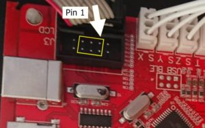

Although a 10 way connector is fitted on the 3D printer controller board the two outer rows of pins are not part of the ISP. Fit the 6 way adapter in the centre of the 10 way socket using the keyway of the socket as a guide to which side is pin 1.
In the Arduino IDE preferences box tick the Show verbose output during upload, this will then give details of the programming process in the lower part of the Arduino window.
Click tools and selected the programmer as USBasp.
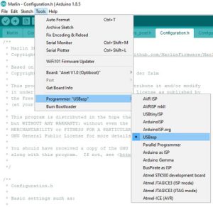

Click tools and set the board to Anet V1.0 (Optiboot).
Click tools and then select Burn Bootloader.
Monitor the lower half of the Arduino window to ensure that programming was successful.
Marlin Firmware:
Location of Marlin firmware – https://marlinfw.org/meta/download/
and download version 1.1.9.1
editors note : version 1.1.xxxx is a version that will fit comfortably into the 8 bit boards – version 2.xx is a very tight fit and may require a different bootloader to allow room for it…
Unzip the file and goto the
\Marlin-1.1.x\Marlinexample_configurations\Anet\A8
folder and copy the two header files into the \Marlin-1.1.x\Marlin
folder.
Open the Marlin.ino in the Arduino programming software, this should open all of the include files at the same time.
Select the Configuration.h tab in the Arduino software.
This is were the fun begins!
I change the following lines of the configuration file for my machine:
- 132 – remove the \\ at the beginning of #DEFINE and in the speech marks enter the name of your printer you wish to display, in my case I used #define CUSTOM_MACHINE_NAME “CTC i3 Pro b”
- 307 – change #define TEMP_SENSOR_0 5
to #defineTEMP_SENSOR_0 1 - 312 – change #define TEMP_SENSOR_BED 5
to #defineTEMP_SENSOR_BED 1 - 537 – change #define X_MIN_ENDSTOP_INVERTING true
to #define X_MIN_ENDSTOP_INVERTING false - 538 – change line from #define Y_MIN_ENDSTOP_INVERTING true
to #define Y_MIN_ENDSTOP_INVERTING false - 539 – change #define Z_MIN_ENDSTOP_INVERTING true
to #define Z_MIN_ENDSTOP_INVERTING false - 543 – change #define Z_MIN_PROBE_ENDSTOP_INVERTING true
to #define Z_MIN_PROBE_ENDSTOP_INVERTING false - 617 – change #define DEFAULT_AXIS_STEPS_PER_UNIT { 100, 100,400, 100 }
to #define DEFAULT_AXIS_STEPS_PER_UNIT { 93.07, 92.77,400.55, 98.30} - 624 – change #define DEFAULT_MAX_FEEDRATE { 400, 400, 8, 50}
to #define DEFAULT_MAX_FEEDRATE { 50, 50, 10, 45 } - 632 – change #define DEFAULT_MAX_ACCELERATION { 2000, 2000,100, 10000 }
to #define DEFAULT_MAX_ACCELERATION { 200, 200, 50, 500 } - 855 – change #define INVERT_X_DIR false
to #define INVERT_X_DIR true - 886 – change #define X_BED_SIZE 220
to #define X_BED_SIZE 200 - 887 – change #define Y_BED_SIZE 220
to #define Y_BED_SIZE 200 - 890 – change #define X_MIN_POS -33
to #define X_MIN_POS 0 - 891 – change #define Y_MIN_POS -10
to #define Y_MIN_POS 0 - 895 – change #define Z_MAX_POS 240
to #define Z_MAX_POS 180 - 1157 – change #define HOMING_FEEDRATE_XY (100*60)
to #define HOMING_FEEDRATE_XY (50*60)
Connect a USB cable from the PC USB port to the controller board on the printer.
In the Tools menu ensure Anet V1.0 (Optiboot) is selected.
In the Tools menu select the port that the printer is on.
Switch on the printer and in the Arduino programming software click Upload, the progress of the programming should be seen in the lower half of the programming window.
Once programmed you should be greeted with a Marlin splash screen on the printer display and be ready to refine the stepper motor movements.
The menu screen should operate a lot smoother with press-and-hold of the push button switches.
For line 617 I used a toothpick and steel rule to measure the distance traveled in the x,y, and z over 100mm using the printer menu (NOTE: I had uploaded the default setting via the bootloader), using the formula of –
New Stepper setting = (Current Stepper Setting * 100mm) / Actual Distance Traveled in mm
editors note : you will need to update the steps by using the m503 gcode with repetier communicating to the printer, to get the current settings…
Then use M92 [axis]calculated value to store the values
Where axis is either x,y, or z and the calculated value is from the formula above.
For example if the calculated steps were 96.28 for the x axis you would type M92 X96.28 and press enter…
I could refine the stepper motor to produce a more accurate print.
Results:
The prints were very much improved with the modifications performed. There is very little z-axis banding (0.1mm) so the effects are hardly noticeable.
The images show the print of robot from thingiverse (and also available the first time you run Cura). The robot on the left is with the original setting and on the right is will all the modification to the printer.
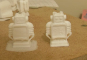

The results were more impressive with a larger print, in this case pencil holder of the terminator head.
editor:
I like all the mods that Ray has done to his printer.
i like the idea of using the steel ruler and cocktail sitck ( toothpick) to measure the distance travelled in one direction.
it could be carried out with an open verier caliper and hte axis pushing on the pin to close it for slightly increased accuracy…
with the USBasp programmer – most now come with the adapter – just make sure you get it in the right position in the center of hte connector.
I am impressed with the work he has carried out to take a cost effective printer from something that didn’t print very good results at all to something that is a very capable machine and his knowledge of his printer will allow him to work within the limitations of his printer.
Thank you for the write up Ray.
and he has kindly supplied the stl files for you to print
download zip files for ctc 3d printer stl upgrades
If anyone has any comments or wants to know more about the CTC 3d printer upgrades then please leave a comment below…
