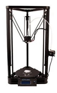
Ok so you have built your printer and set it up.
You try and print on your delta , and it sticks in the centre but nowhere else – so what do you do now?
You read this delta printer calibration guide about calibrating the z axis to find out how to get your nozzle running flat across the bed.
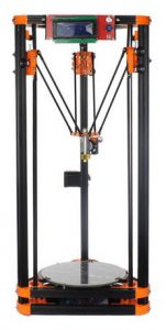

I really struggled with this after building my kit, as it would be right across part of the diameter them curve upwards toward the outer edge, thinking I could ‘ get away with it’ I started printing- only to find I couldn’t. Prints wouldn’t stick and layers would separate.
I bought a delta printer kit, so much cheaper than the ready built ones.
My printer is a Renren3d LE delta printer. Running the delta 3d marlin firmware version 1.0.0
To find out how I built my renren3d le delta printer kit visit these posts. Part 1(initial), part 2(frame), part 3(electronics), part4(programming).
When I first built this machine, I knew very little about delta printers – except that I liked the way they moved.

Now I can explain what is happening to move the nozzle across the build platform. How to calibrate it, and what some of the problems are.
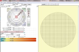
I use Pronterface as the software on the computer to talk to the machine, I found this to be the most stable.
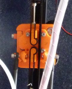

At the top of my axis carriages is an M3 screw and nut for mechanical adjustment.
My build platform is glass over a heated pcb.
I have now stuck kapton tape over the glass plate as I struggled to get the PLA to stick to the glass plate.( another story )
After setting up the mechanics and wiring up the electronics, first switch on was a nervous moment. It was fine – no smoke or sparks and the display said the right things. Phew!!
After setting the Z height.
Reading the manufacturers instructions on what to do next left me a little puzzled. But I followed them, and got nowhere fast.
Put down the auto calibration switch, type into pronterface ‘M32 S5 M0.1’ and wait. Take the answer and double it add it to the rod offset and then recompile. Try again. I carried this out a few times and it was still getting an offset.
So I sat back and trawled the internet for a solution. Yes there are some but all of them required that you knew a lot about the software or the operation of the printer or other things.
So I decided to create a step by step delta printer calibration guide.
At the end of this post is how the printer works and what the various offsets mean, in the mean time you came here to calibrate your printer – so lets get on with it.
Step by step delta printer calibration guide : Z axis
As I stated above I am using pronterface as the computer software.
Pronterface custom buttons
With this software various sites stated that you add custom buttons, press the plus and you can edit the button.
I couldn’t find the plus, after digging into the software I found you had to add a button manually before you can click the + sign to add another button.


So in pronterface you need to type into the lower right box, where you send the controls to the printer.
button 1 “home” g28
You can copy and paste this command into the box and press enter, what you should see is a button appear in the centre panel named home.
Make sure your printer is connected – plug in the usb cable and drop the port box down, you should see a port listed. Set the speed to 250000 and hit connect.
There should be a lot of words scroll up on the right hand pane, the printers display should blank momentarily and restart. The last line should be sd card ok, or sd card not present. Depending on whether you have inserted the card.
If you click on the ‘home’ button your printer will go home.
This will take the nozzle to its highest position in the center.
Brilliant – saves you remembering the command or typing it in every time.
So now you want to setup another few buttons
One for checking the position of the nozzle, testing the endstops, going to the three posts so you can manually setup your printer.
Now you can either click on the + next to the button and enter the information – or you can copy and paste each line seperately into your machine – as before.
button 2 “position” M114
button 3 “endstops” M119
button 4 “x_post” G0 F3000 X-65 Y-38 Z2
button 5 “y_post” G0 F3000 X-65 Y38 Z2
button 6 “z_post” G0 F3000 X0 Y65 Z2
button 7 “centre” G0 F3000 X0 Y0 Z5


button 8 “auto_cal” M32 S5 M0.1
Now you have 8 buttons added to carry out the most useful functions.
If you now press the ‘position’ button the panel will report the distance for the z travel.
Initial settings
The adjustment screws and nuts at the top of the carriages should be tight and in about 2/3 of their distance. Allowing 3-4mm of movement in both directions.
The end stops must be tight in their rails. Just check them again. This will affect the calibration if they are not tight. The printer does thump into these when it goes to the home position and you really don’t want them moving – even by 0.1mm
So now after setting up pronterface with buttons and checking the end stops we can finally get to setting up the printer.
Initial setting of the posts
Click on the ‘home’ button, I found that the printer will switch off the power to the stepper motors and the nozzle will droop, so to be sure we are at the top click on the ‘home’ button before beginning this calibration.
Click the ‘x post’ button, your printer nozzle will head towards the x post and stop above the build platform by about 2mm.

Why did I do this? Well if your printer has to be adjusted upwards then the nozzle would have just rammed the glass plate, so better to be safe than sorry.
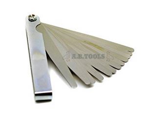
Using either a piece of paper – or as I prefer now a 0.1mm feeler gauge, lower the nozzle slowly using the z movement. Near the circle in the top left corner.
If the paper or feeler gauge becomes trapped before z=0 then stop.
If it looks a long way above, click the Z move 1 button, then go down by 0.1 until you reach z= 0.
One of two things will happen, the paper or feeler gauge will be tight or loose.
If the gauge is loose then you need to lengthen the travel on this axis- you are working on the x post mechanical adjustment only.
Using a spanner (5.5mm) to hold the nut and an allen key (M3) in the screw rotate it anti-clockwise to raise the screw. I used a pair of pliers to hold the nut as I didn’t have the right spanner at the time.
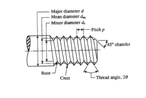

For every turn (pitch) of a M3 screw you will raise – or lower – it by 0.5mm on the thread.
Looking at the gap you have guestimate how far you have to turn the screw and make sure the nut does not come loose while turning the screw.
You could measure the gap with the rest of the feeler gauges and then you know how far to turn the screw, or you could fold a piece of paper until it just fits under the nozzle and measure this with a vernier gauge, again you then have a good idea of the rotation required.
Now click the ‘home’ button again.
And the ‘x post’ button. You knew that was coming, didn’t you!!
Lower the nozzle again and get the height above the build platform set so that is is dragging on the gauge.
With the paper, you want it so that the paper feel like it will bunch up but still move. What you don’t want is that the paper will not move under the nozzle.
With the feeler gauge you can feel the resistance of the nozzle starting to press onto it.
Once this is set – it may take a few attempts to get it right, go onto the y post and perform the same process.
Press the ‘home’ button, wait for the printer to go to the top and stop, then press the ‘y post’ button, lower it onto the gauge and adjust the screw as necessary.
Then the z post.
You have now set the three posts for their zero height.
The interesting bit is when you go to the centre.
So click the ‘home’ button, then the ‘centre’ button.
This will stop 5mm above the build platform, to prevent a nozzle crash.
Lower it slowly onto the gauge, as you did with the posts.
Again one of two things will happen – either it will become tight before z=0, or it will reach z=0 and still be loose.
z>0 when gauge becomes tight

If it is tight then make a note of the z position where it feels right.
I found that it became tight at z=0.4
You will need to open the configuration.h file in an editor- like notepad++.
Locate the line where it says
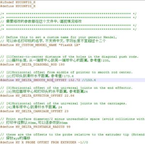
#define DELTA_SMOOTH_ROD_OFFSET
There should be a number after this.
NOTE: in the software supplied for the Renren3d LE 3d printer this is found in myconfig.h rather than configuration.h
There is a value in configuration.h but it is overwritten with the value from myconfig.h.
The value of z to adjust the rod offset to correct for the error.
Adjusting the value of #define MY_DELTA_SMOOTH_ROD_OFFSET by 1.2mm adjusted the real z value by 2mm with my printer, so my ratio was 1.67 (2/1.2).
With this I can calculate the correction value to add or subtract to the rod offset.
So 0.4 X 1.67 = 0.668, this has to be added to the value of smooth rod offset.
The initial value of smooth rod offset was 153.4.
we need to add this the calculated error value from the programmed value in a downwards direction.
So 153.4 +(– 0.668) = 152.72
If you enter this with // after it you keep the old values – only edited out
#define MY_DELTA_SMOOTH_ROD_OFFSET 152.72 //153.4
The other thing I tend to do when programming is to alter something I can see – only so I know the programming has taken effect.
So in our case we have the name of the printer in this file so I add a number to the end, this is incremented when I update the program until 9 then decremented back to 1. this gives me a sure indication tat it has changed to what I have just done.
#define MY_CUSTOM_MENDEL_NAME “FlashX LX” becomes
#define MY_CUSTOM_MENDEL_NAME “FlashX LX1”
if you need to do this a second time then the name becomes
#define MY_CUSTOM_MENDEL_NAME “FlashX LX2”
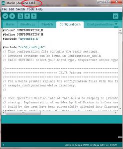

You need to save myconfig.h
Then open Marlin.ino in Arduino 1.0.6
NOTE: Not using this version of the arduino compiler causes errors when compiling the software.
Remember to hit the disconnect button in pronterface, the computer cannot connect two programs to the same port.
Click the compile button on the arduino interface. And wait for it to upload to the controller.
You will receive a success message when it is done, the controller will reset and you will see the name of the printer change. You know it is done.
If you have to recompile the software, I found that it will not pick up the recently saved myconfiguration.h. So I had to close and reopen the arduino software for it to correctly use the latest file. I am sure this is something that has been addressed in later versions, but as stated above you will get compiler errors using other versions.
Now reconnect pronterface and click on the ‘home’ button.
What you have just done is to add an offset in software to the centre.
If you click on the ‘centre’ button you will find that it is 0.4mm too tight.
So what do you need to adjust to see the affect of this?
You need to click the ‘x post’ button, when going down slowly you should find that it goes to z=0.4 and is tight. You need to adjust this out with the screw.
Repeat for the other two posts.
What has happened is that the cone centre has been corrected in software but the hardware post positions have been lowered by 0.4mm.
You need to raise the post positions by 0.4mm, this should now be flat across the circle of calibration you have just done.
I produced a calibration circle with three 120 degree arms – turned out to look like the CND symbol. But it shows whether your nozzle is running flat across the calibration circle.
Here’s the stl file. 135 mm dia cal
z=0 when gauge is still loose
This indicates that the nozzle needs to be lowered down to correct for an upwards cone.
Ideally you need to use a gauge to find the gap, or you can do as I first did. Guestimate the gap and correct for a tight situation.
The error needs to be added to the smooth rod offset variable.
This on my printer is found in a myconfiguration.h file.
There is one in the configuration file but it is overwritten with the value in myconfiguration.h file.
So you are looking for
#define MY_DELTA_SMOOTH_ROD_OFFSET
This has a number after it as a start value.
You will need to add the error offset, scaled with a multiplier. In my case the multiplier was 1.67, so any error values are multiplied by this before adding to the smooth rod offset value.
So if the gap was 0.4mm, you multiply this by 1.67 getting 0.668.
this you add to the value of the my smooth rod offset variable.
152.72 + (+0.668) = 153.39 ( only go to two significant digits)
If you enter this with // after it you keep the old values – only edited out
#define MY_DELTA_SMOOTH_ROD_OFFSET 152.72 //153.4
As stated above I will also change something I can see to ensure that the reprogramming has been done.
You will always see the name appear on the lcd so this is what I use.
#define MY_CUSTOM_MENDEL_NAME “FlashX LX” becomes
#define MY_CUSTOM_MENDEL_NAME “FlashX LX1”
if you need to do this a second time then the name becomes
#define MY_CUSTOM_MENDEL_NAME “FlashX LX2”
Save the file, load up the arduino software.
Remember to disconnect from pronterface.
Look for the success acknowledgement at the bottom to show that it has been programmed.
You will also see that the display shows the new name.
Connect with pronterface.
Click on the ‘home’ button.
If you go to the centre you will find there is still an error, you need to reset the mechanics.
You need to click on the ‘x post’ button.
Slowly go towards zero and you should find that it is loose. The gap should be the offset you added to the rod.
As before you need to correct the error with the screw, making sure the nut stays tight.
Click on the ‘home’ button, and then go to the x post again to see the result of the adjustment.
Correct again for errors.
Repeat this correction on the other posts.
Now go to the centre position and see if the software correction has adjusted it enough to be within 0.1mm of the build platform.
If not – you can curse now, as you have to correct this error in software, as before and redo the hardware posts.
Yes it takes time but it is worth doing.
One thing I will investigate is to add springs to the build platform and take out the error for the centre here.
Then readjust the posts as before and see if that works. It has got to be simpler that reprogramming all the time.
I have produced a calibration circle with three arms at 120degrees apart. Once you are happy with the calibration then try printing this out.
See if it stick down all the way around and correct if it doesn’t.
It may show that your build platform is not flat across its surface.
The stl file is here.135 mm dia cal
The other thing to do is to mark the position of one of the posts on the glass plate, so you can put it back into the same position every time you take it off. And the same way up.
Which you will do either to remove a finished piece which is really stuck on or to clean the glass plate.
I would suggest either error correcting fluid or kapton tape. Scratching the surface may weaken it and cause it to crack under heating.
Finishing up
Hopefully now you have a delta printer with a nozzle which glides flatly over the build platform.
Outside the calibrated circle your printer may go up or down so make sure you print within your calibrated circle. So if you can set the post positions wider then do.
Use the manual XY circle in pronterface to set the position of the nozzle in front of each post at the widest you can from the centre. Make a note of the position X and Y. Edit the post buttons by right clicking on them and picking the edit function.
Make sure that you adjust the positions symmetrically, so if the x button becomes
x-70 y-42 z2
Then the y post becomes
X-70 y42 z2
And the z post becomes
x 0 y70 z2
The centre you can adjust the z height if you want to, but I felt that 5mm gave it some margin to work with.
I really hope this has not been to confusing and has helped you adjust your delta printers z axis.
I found that the auto cal was not working and I needed to find out what was going on.
Technical explanation of how the printer operates.
If you think of the printing area as a cylinder.
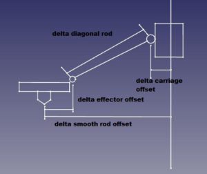

The software works via pythagoras’s theorem of 90 degree triangles.
This is why it needs to know some details about your printer.
Like the distance from the post to the smooth rod end, the distance from the nozzle to the smooth rod end, and the smooth rod length.
The smooth rod offset you have just been changing is the radius of the printer.
To this value is subtracted the post to smooth rod end offset and the nozzle to the smooth rod end. This leaves one of the sides of the 90 degree triangle.
The smooth rod length is the hypotenuse of the triangle, leaving the controller to work out the other. This is correct for the zero position.
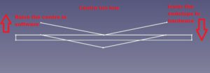

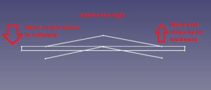

Any error in this length will show itself as a cone – either up or down as you move away from the centre position. This is the reason you need to fix the post positions first, then check the centre position.
If you have any questions about the process or additions to make it simpler then please add a comment to the Delta printer calibration guide : Z axis post so we can all learn your tricks and build better printers.
Many thanks for reading
Phil

Button 8
SENDING:G32 S5 M0.10
echo:Unknown command: “G32 S5 M0.10”
In the text above this, it is set for M32 S5 M0.10
Now updated in the post – thanks for spotting it