Another post in the 3d printer project ideas series. This one gives you a walk through for the Autodesk 123design software. To create a stand for an Apple Mac power block.
Background
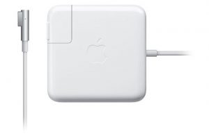
My partner has an Apple Macbook Pro. The power supply for this unit is an external unit with mains input and dc output. The mains input is via a lead, which plugs into the side of the power block. The dc output is fed to a magnetically attached connector to plug onto the Macbook Pro
A while ago the power supply failed. It stopped charging the battery on the laptop.
Investigating it, as any engineer would, showed that the dc cable had shorted internally. It appears that this is a weakness in the way apple have manufactured these units and they will fail eventually where the dc cable comes out of the block, especially if the user winds the cable back up onto the cable clips on the power block.
Repairing this cable, the unit works again.
In the meantime we had a Chinese unit, this failed catastrophically. I opened the unit to find that something had blown up – black mark on the inner of the lid. Could I find it? No!! the fault was the same – output dc cable shorted. really frustrating, but it did show that the original apple unit was output short protected and would recover.
Design
Anyway to the project, my partner wanted the power block to stand up, the unit is 79mmx79mmx29mm and laying down, the lower side was getting very hot. So the idea was to stand it up to enable more airflow around the device.
Trying it unassisted the unit just kept falling over, so in steps 3d printing.
I think to myself I can design something to do that easily.
The grey matter starts churning.
The design flow goes something like:
It is too tall to stand up so it needs outriggers.
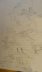

It also needs to support the sides from both sides.
So flat feet extending sideways and up the sides.
Easy to remove and lay flat after use.
Possible expansion of cable tidy to not strain the output or input cable
out came the sketch book and pencil – yes I still do it this way.
I find it quicker than using a computer. I may investigate a drawing package for the tablet but in the meantime paper and pencil.
The first design was a typical flat piece for the feet with two uprights for the sides of the unit.
I would need two of these, maybe one would get lost? Will need to print off another one. So that idea was put to one side, if I can’t come up with anything else then ok.
The second idea was along the length of the block, with a support at either end and feet out to the side. It’s starting to get large. So possible but don’t stop there.
The next idea was a single sided foot with two supports, one either side of the power block. Ok, getting more original, but if one breaks gets lost then it will fall over.
What about combining these two?
Have three uprights and three feet?
One on the left and two on the right?
With feet extending out?
Small compact and efficient
A single piece and not too large.
This is the design I went with.
Getting it Sorted
I have been trialling Cubify Invent software and after watching the training videos from cubifyfans blogspot, getting the idea of the software it was very easy to produce a fairly complex item – see the salt cellar repair(part 1) and part 2.
The trial has now run out so I was either going to have to purchase the software or try another one.
I had downloaded Autodesk 123design a while ago and never installed it, so this was an ideal time to get it onto my computer and learn it.
After installing it and running it, you are presented with it’s home 3d screen. And…
I played around with the menus, solids and sketches. But had very little headway into the design. I thought I had heard this was supposed to be a very easy cad to learn.
I found this book 3D Printing with Autodesk 123D, Tinkercad, and MakerBot
It covers the basics of 3d printing along with the rest of the suite of software. So although it was not completely dedicated to 123 design it gives enough information along with a few walk through examples to get you started.
Watching the online get started videos from Autodesk was a bit annoying, the person doing the videos assumed a high knowledge of the software and clicked here and there and then tidied up the sketch before extruding it, all in two minutes. No I never went back.
So how to draw up the model to get it printed.
The CAD Process
123design can be thought of in two ways.
One way is like a cnc machine, you create a piece big enough to cover the whole of your model and you then subtract material until what you have left is the object which you want.
The other is to break down what you want into basic shapes, box, cylinder, ball and cone amongst others. These are placed together in a 3d space to create the model you want.
In this tutorial I have gone with the second method. Using basic shapes to make up the model.
In the future I will try the other method and compare it. Similar to a sculptor removing material to find the statue.
I have decided not to do videos of these tutorials at the moment as when I watch them I find it difficult to follow along with the training, having to pause the video and remember what was just done. With the written word you can just refer back to it easily.
So we now know what we are after, three L shaped brackets tied together with a flat slab.
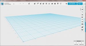

Open the 123 design software and you should be presented with this screen.
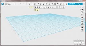

What we need to do is to place a rectangle to fit underneath the power block. This will be 30mmx50mmx2mm. So hover over the primitives menu. A sub menu will appear click on box.
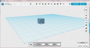

When you place your mouse over the grid you will be presented with a box, of dimensions 20mm on all sides. We need to change these to suit what we want.
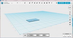

As the length is highlighted we change this first, set this to 30 and press [tab] it will highlight the width, type in 50 and press [tab], for the height I have selected 2mm, so set the highlighted height to 2. the visual box on the screen will also change in real time and for this one you can place it where you want. I chose one of the darker lines for a reference and clicked with the mouse.
Your first shape is placed.
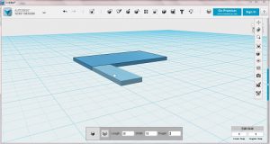

We now add another box, so hover over the primitives menu and go down to box, click on it and set the box parameters to length 30, width 10, height 2. place it aligned with the left back corner as shown in the figure and click the mouse to place.
You have added one of the feet.
As all of the feet are the same size we can copy and paste this box.
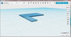

With the mouse click on the box, the outline should go and stay green.
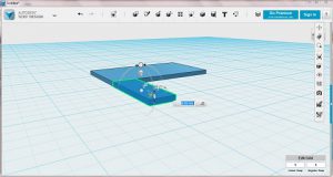

Press [ctrl] and tap the ‘c’ key. This will copy the box. Then press [ctrl] and tap ‘v’ this will paste a second box. It may not be obvious but the movement arrows show that it is there.
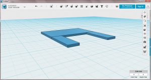

We need to move it to the right so click on the right going arrow, this should turn yellow. You can either drag it using this, click and hold the mouse while moving in the direction you want to go, or you can type the distance into the box, as this is blue you can just type the number in, so type in 40 and the box should move 40mm to the right.
If this doesn’t happen and it moves in another direction, you can either move it back manually or I tend to press [ctrl] and tap ‘z’ this is the undo keys. You will need to copy the box again and try again. It can take a few goes at the start to get used to the keys and clicks, I am still getting used to them.
You end up with a second foot at the other end at the back of the original block.
We now need another foot on the other side of the base block, so copy and paste the original foot again.
This time we want to click on the front arrow, we will move it backwards first. If we typed a positive number into the box it will move in the direction of the arrow. This would move the foot away from the base block, no good. So with this co-ordinate system we can type in a negative number. This will move it in the opposite direction of the arrow – towards the front of the base block. Type 60 into the box and the foot should align itself to the front right hand corner.
Now we need to move it to the middle of the base block. So click on the right arrow and type 20 into the box. This will move it to the centre position.
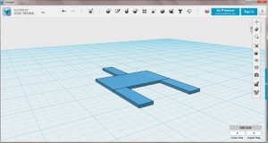

You end up with a mode like this:
At this point it is worth saving the model. I tend to work off my computer and as my internet is not fully reliable I will save it to my local computer. Click on the little down symbol to the top left of the screen. Move the mouse down to save a copy and out over my computer.
I have setup a folder in my documents for Autodesk projects, click on the folder you want to save it to, name it what you want to – in my case ‘psu stand 2’ and click on ‘save’
You now have a point to go back to is it all goes horribly wrong. It is a good idea to get into the habit of saving your work regularly. This way you can always just go back a bit to the last save rather than starting from scratch. Don’t worry you will forget to do this and it will go wrong – it is a bit like doing a backup – everybody will do it and knows it makes sense but later – until your computer crashes and you think I should have backed it up. So start getting into the habit of saving after every few moves and especially if you are trying out a new technique. These always go wrong and you will find some commands without a ‘go back’ command – and it is sometimes easier to go back to what you know.
Now we need to add the side pieces, very similar to the feet, adding boxes to all three feet in the upright position.
Again hover over the primitives menu and click on the box.
Come back to the grid with it and type length 2, width 10, height 40, position this as close as you can to the edge of the base block where the foot is at the rear left corner.
To check where you have positioned it you can rotate and zoom in onto the model.
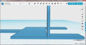

To rotate you press the right button of the mouse and hold while moving the mouse. A two ellipse symbol will appear and the model can be rotated.
To pan the model – or move it across the screen to reposition it you press the middle mouse button, this will bring up a pair of crossed arrows. You can now drag the model across the screen.
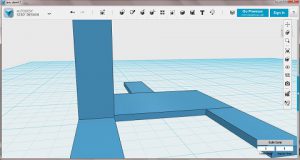

Using these two controls you can look at the upright and see whether it is at the edge of the base block and inline with the foot.
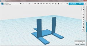

If it is you can go no to add another upright, in the same way as we did with the feet. Click on the upright to highlight it and then press [ctrl] and tap the ‘c’ key to copy. Then press [ctrl] and tap the ‘v’ key to paste. Use the arrow keys to move it to the right by 40mm.
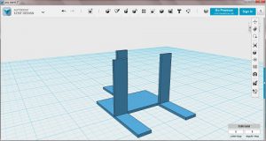

Copy and paste another upright for the front, move this away from you by 32mm ( 30 mm for the base block and 2mm for the thickness of the upright), then to the right by 20mm. This should position it over the foot at the front.
This has now completed the basic power supply clip, but sharp corners are stress raiser ( where things tend to easily break). They are also a potential hazard to cut you. So it would be nice to round the top edges of the uprights and add a fillet (rounded fill) into the bottom between the uprights and the feet.
To round (fillet) the top edges of the uprights you select the edges you want. We will work on the back left upright first.
Rotate and zoom in ( scroll the middle wheel or click on the
magnifying glass to the right hand side) so you can see the top of the upright.
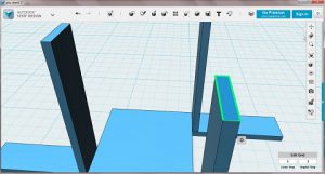

Click in the middle of the upright top box. And then click on the top edge – this will highlight in green. Press [shift] and click on the other 3 edges so that you have all four top edges highlighted.
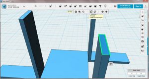

Now scroll up to the modify menu and find the fillet selection. Click on this.
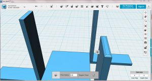

A box will appear at the bottom of the screen. Make sure that all of the edges are still highlighted and type 0.5 into the box and press [enter]. The top corners will appear rounded.
You have filleted the top of the upright.
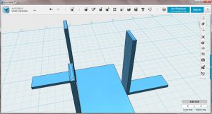

Now go on to do the other two uprights.
We are going to add a fillet between the upright and the foot to add a little strength to the lower corner. So navigate back to the home position, by hovering close to the cube in the top right of the screen and click on the house symbol when it appears.
The upright and the foot at present are separate parts at the moment. This cad system cannot fillet between two separate parts, so we need to join then – or merge them into one part. I did this first by grouping them but this doesn’t merge them to allow the filleting as it keep them as separate parts and just selects all in the group. You need to use the merge selection .
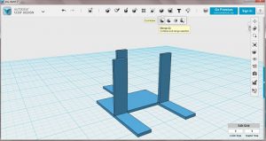

Hover over the combine menu and click on the merge selection.
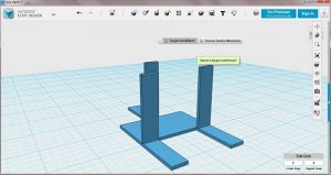

A new menu will be on screen showing target solid/mesh and source solid(s)mesh(es).
This allows you to select the target solid or mesh to merge the objects with – so click on the foot. This will now have a green outline and the onscreen menu will change over to source sold(s)/mesh(es).
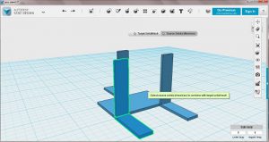

You now click on the upright as we only want these two we are finished, but if you needed more you could hold down the [shift] key and click on all the solids you want to select.
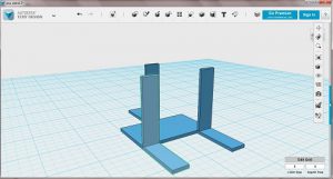

Now if you press [return], hover the mouse over the foot. You will see that both the foot and upright are highlighted meaning that these parts are now combined.
If you now zoom in so that you can see the join between the upright and the foot clearly.
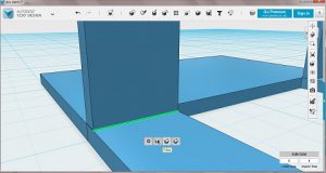

Click on the foot to select it. A sub menu appears at the bottom of the screen. None of these operations are what we want. So if you click on the edge between the foot and upright ( it will highlight in green when selected) a little gear icon appears.
Hover over the gear with the mouse pointer and move to the right to select fillet.
Click on this to bring up the fillet menu.
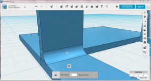

Set the fillet radius to 2.
Untick the tangent chain selection.
You will see the fillet in the bottom corner.
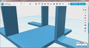

Press [return] to accept this and go and merge the two other feet and uprights before filleting them.
Click on the home selection, when you move the mouse over the box in the upper right of the screen.
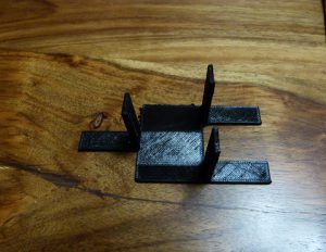
This is the part I printed.
So save the model.
And then navigate to export as 3d.
On the mesh tessellation setting menu presented. Click on medium and combine objects.
Click on ok.
Type in the name you want to save it as and click save.
Post CAD Processing
You can now load your stl model into your slicer for your printer.
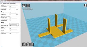

I am using Cura here but it can be any of the program, either generic or bespoke to your printer.

You need to translate the stl file – what the cad saves it in for 3d printing, to code the 3d printer can use to position the print head in 3d space – G-code.
Setup the correct parameters for your printer and save the file.
Transfer it to your printer and watch the magic begin.
After it has printed and cooled, remove it from the build platform and try your power block.
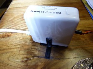

Mine fitted first time, it is now in constant use as a support for the power block.
I hope you have enjoyed this ‘how to’ tutorial.
If you have any comments please leave them in the box below.
Future Projects in the 3d Printer Project Ideas Series
If you have any projects which you would like a hand with, to do with 3d printing, please contact me via the contact page. there will be others in the series 3d printer project ideas as soon as I am able to find other things around the house which need fixing.
Thanks for reading
Phil
